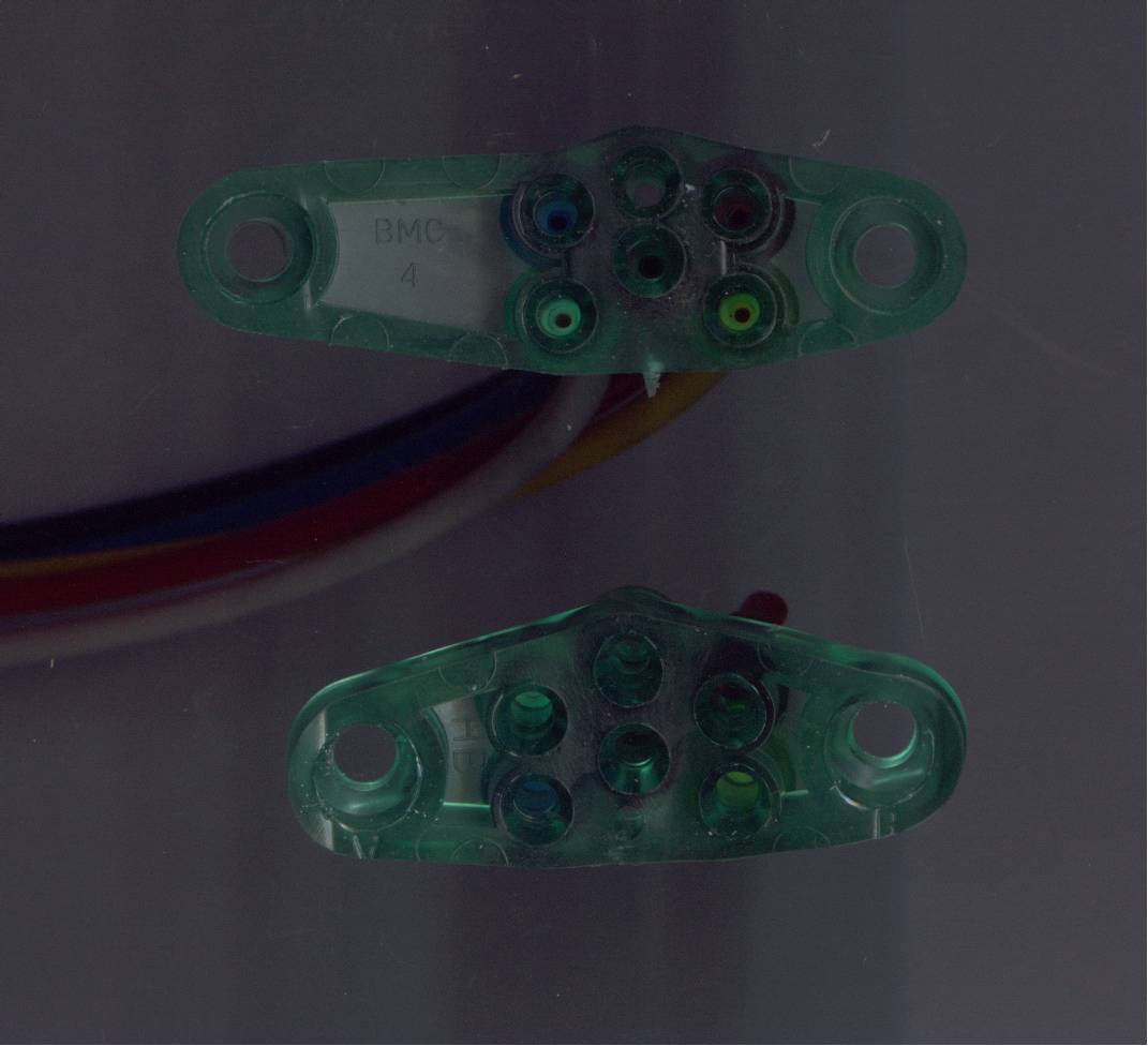
| Connector |
Wire Color |
Where |
Function |
Notes |
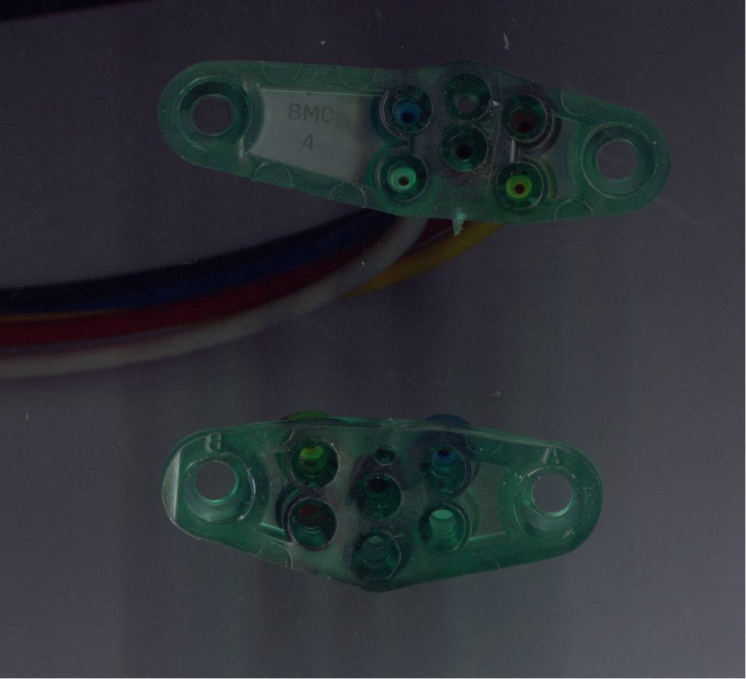
| Grey Connector C227 |
Twisted Pair ([Pink/Light Blue] &
[Tan/Orange]) |
Junction at obd2 diagnostic port near gas pedal |
Multiplex SCP Bus for coolant temp & vehicle
speed data |
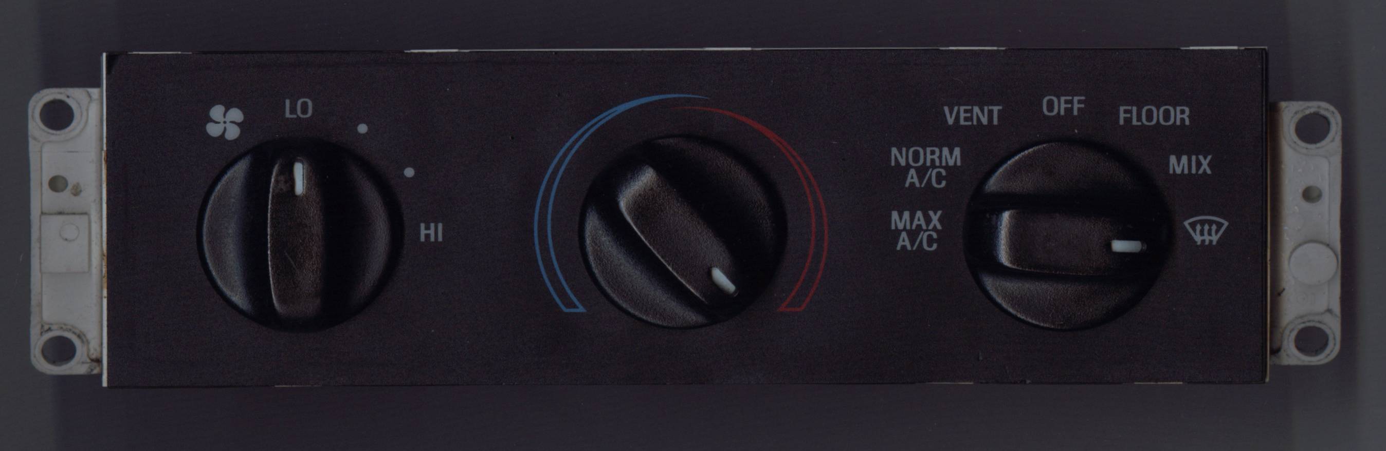
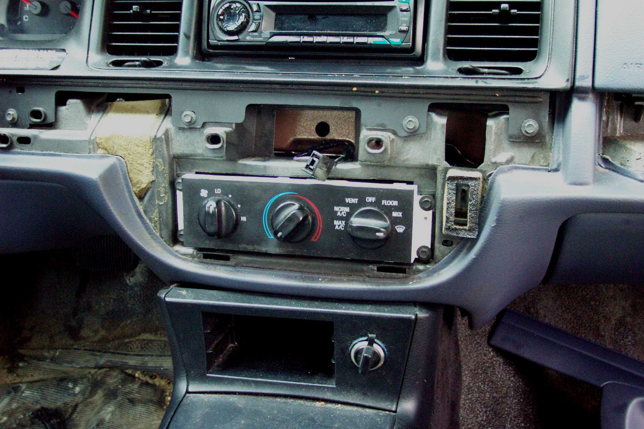
Instead of ghd seperate cold engine lockout
(celo) switch used on antiquated crown vics, 1995+ ones recieve coolant
temp data from the pcm via the data bus |
| Grey Connector C227 |
Light Green/Yellow |
At drivers fuseblock |
Constant +12V |
Inititally was using the cigar lighter to power
this wire but later moved the wire to
a circuit because it's bad if the heater stops working if you plug in a
defective cellphone charger or other accessory |
| Grey Connector C227 |
Purple/Orange |
At driver's fuseblock |
Switched +12V |
A switched ignition +12V wire is present at the
old manual hvac controls. But I already had a switched +12V wire
connected to the proper circuit on the
fuseblock from another project. |
| Grey Connector C227 |
Light Blue/Red |
At Radio or LCM |
Variable Voltage Dimming Output of LCM |
|
| Grey Connector C227 |
Black |
At old manual hvac control head wiring |
Ground |
|
| Grey Connector C227 |
Dark Purple |
At old manual hvac control head |
A/C low side cycling switch |
Do not confuse this wire with the other purple
wire that's used for the blend door actuator |
| Black Connector C228 |
Orange/Black |
At old manual hvac control head or at cigar
lighter plug |
PWM Dimming output of LCM |
|
| Grey Connector C227 |
Pink/Black |
Construct New Harness |
Common sensor ground for interior air temp &
sunload & exterior ambient air temp |
|
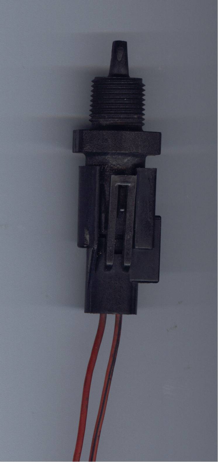
| Grey Connector C227 |
Blue/Orange |
Construct New Harness |
Exterior Air Temperature Feed (Underhood in
front of horns) |
|
| Grey Connector C227 |
Brown |
Construct New Harness |
Sunload Sensor (Far passenger dash near a-pillar) |
|
| Black Connector C228 |
White/Orange |
Construct New Harness |
Interior Air Temperature Sensor (Near hvac
vontrols) |
|
| Grey Connector C227 |
Yellow/Light Green |
Yellow Light Green |
Blend door actuator harness |
You can catch the blend door actuator harness at
the connectors where the body and dash harnesses meet under the
glovebox. Or you can just run 5 new wires from the blend door actuator
pigtail to the eatc control head. |
| Grey Connector C227 |
Red/Light Green |
Dark Blue |
Blend door actuator harness |
|
| Black Connector C228 |
Bright Purple (Below orange/black) |
Purple/Orange |
Blend door actuator harness |
Do not confuse this wire with the other purple
wire that's used for the a/c cycling switch. |
| Black Connector C228 |
Red/White |
Red/White |
Blend door actuator harness |
|
| Black Connector C228 |
Brown/Light Green |
Gray |
Blend door actuator harness |
|
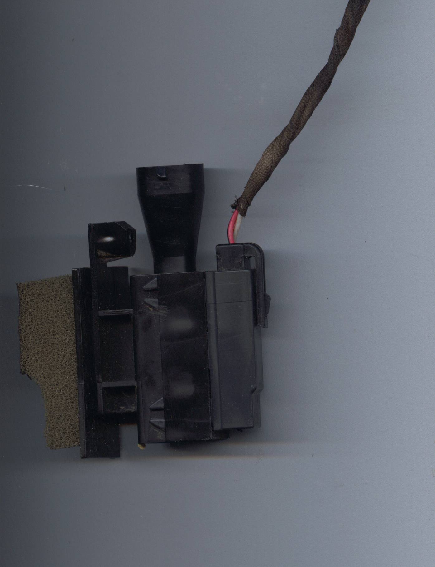
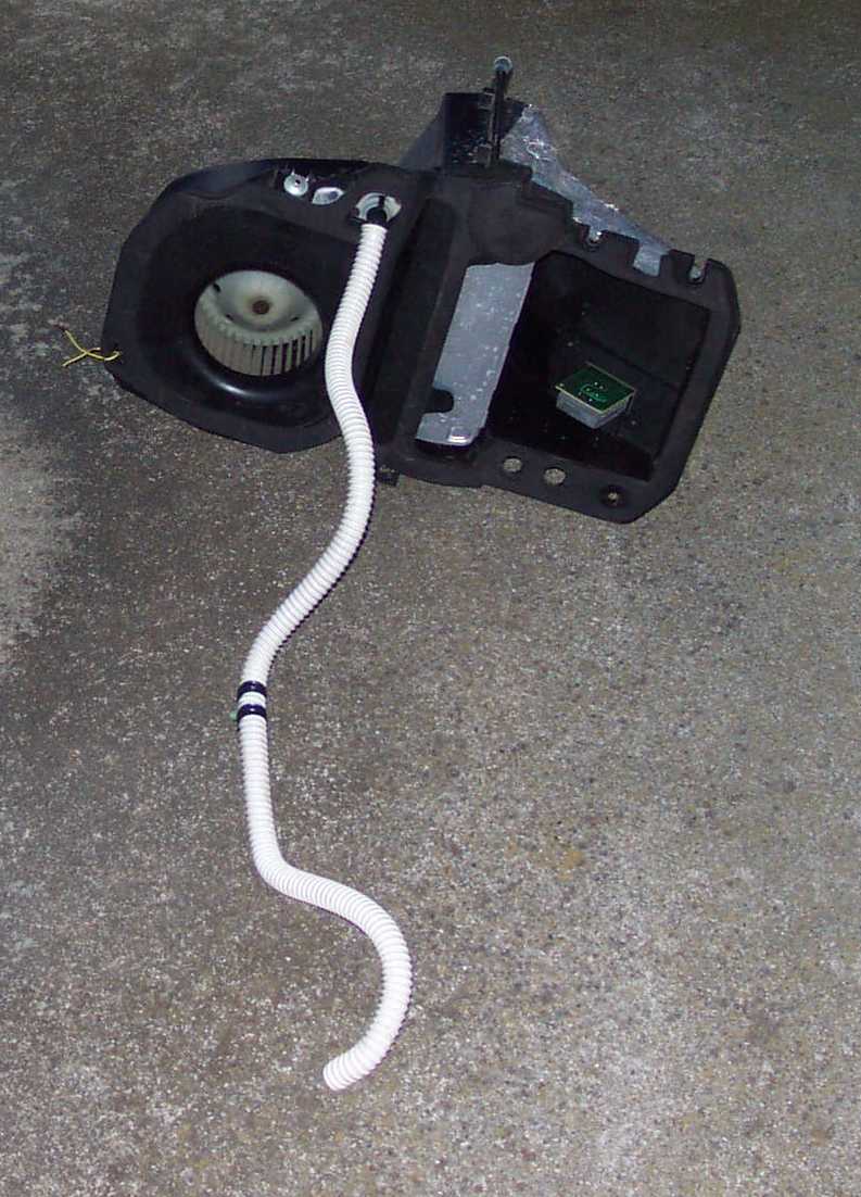
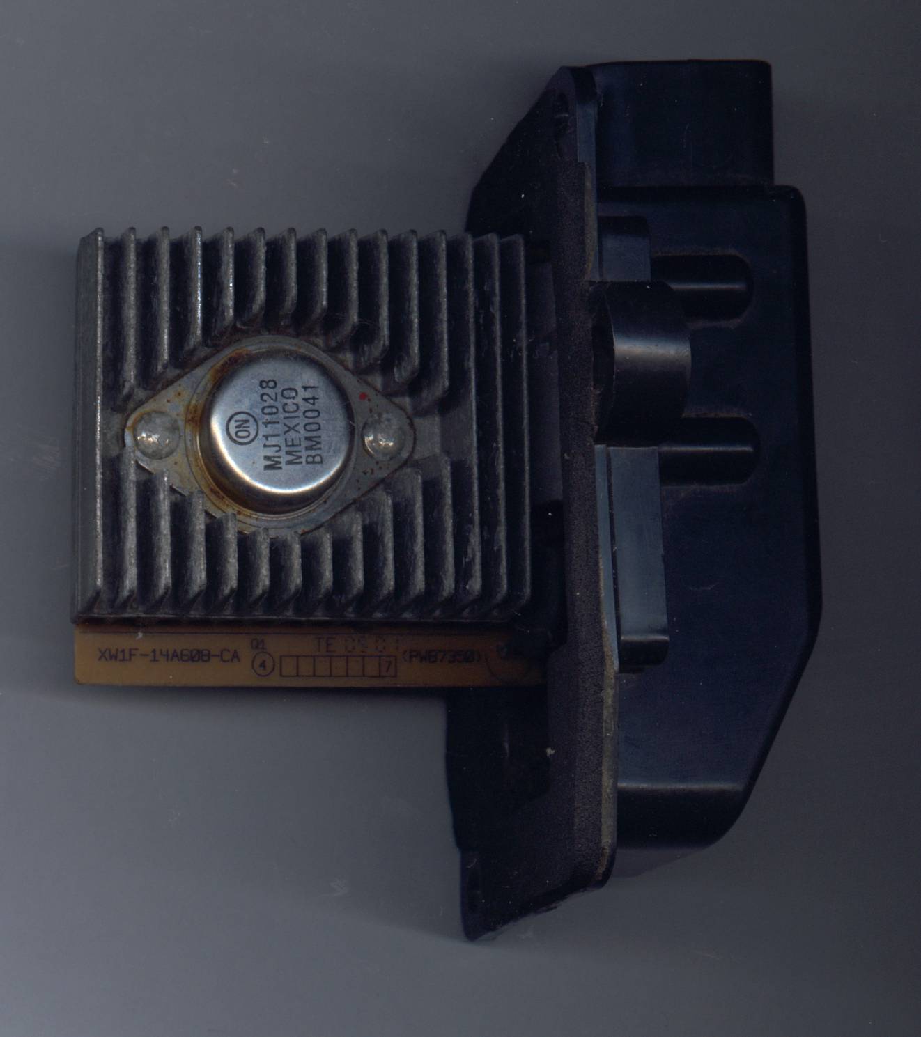
| Black Connector C228 |
Light Green |
To Blower Speed Controller |
High speed relay |
Applying +12V to this wire engages a relay
inside the controller that provides a direct
path to ground for the blower motor. |
| Black Connector C228 |
Yellow/Red |
To Blower Speed Controller |
Variable speed control
signal |
Do not apply +12V to this lead or you will
damage the speed controller by burning traces off the circuit board. To
test whether this portion of the controller works, apply +12V through
an inline resistor somewhere in the 1k to 10k ohm range. |
| Black Connector C228 |
Light Blue/Orange |
To Blower Speed Controller |
Feedback signal |
This output is connected through a 1k ohm
resistor to the high current blower motor feed. |
| Black Connector C228 |
Red |
Not Used |
Digital dash english/metric switch |
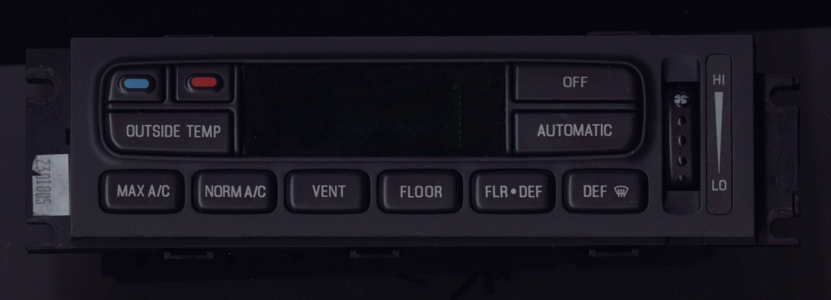
Installing a digital dash into my P71 would be
trivial compared to adding eatc. But I prefer the feel of analog
instrumentation at the moment. |