|
SECTION 501-12: Instrument Panel and Console
|
2002 Crown Victoria/Grand Marquis Workshop Manual
|
REMOVAL AND INSTALLATION
Instrument Panel
Removal
 CAUTION: Electronic modules are sensitive to static electrical charges.
Avoid exposing any modules to static electrical charges, as this may cause
damage to the modules.
- Remove the driver air bag module. For additional information,
refer to Section 501-20B .
- Remove the passenger air bag module. For additional information,
refer to Section 501-20B .
- Close the glove compartment.
- If equipped, remove the floor console. For additional information,
refer to Floor Console in this section.
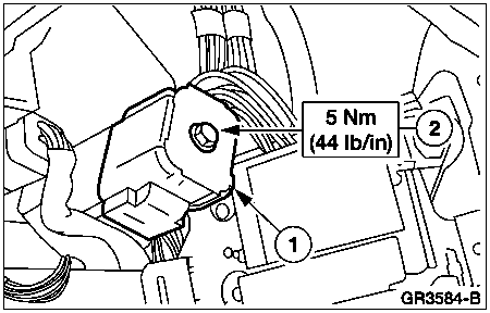
- Position the speed control servo aside.
- Disconnect the electrical connector.
- Remove the nuts.
- Position the speed control servo aside.
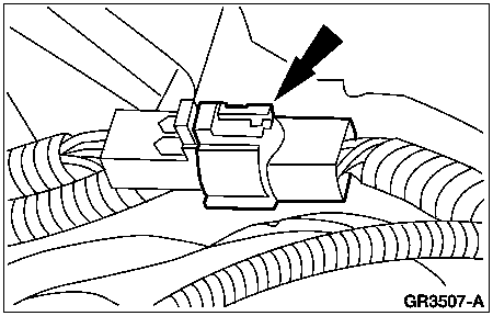
- Disconnect the LH engine compartment in-line electrical connector.
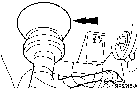
- Release the wiring harness locators.
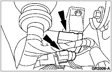
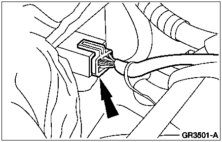
- Disconnect the brake fluid sensor electrical connector.
- Disconnect the windshield wiper motor electrical connector.
- Release the wiring harness locators.
- Disconnect the LH engine compartment in-line electrical connectors.
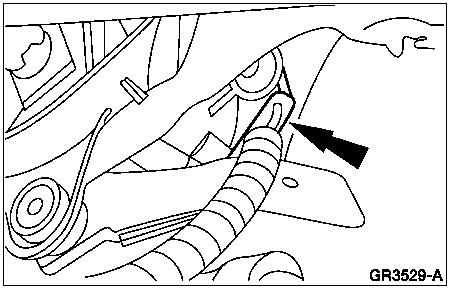
- Unseat the LH wiring harness grommet.
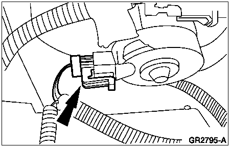
- Disconnect the blower motor electrical connector.
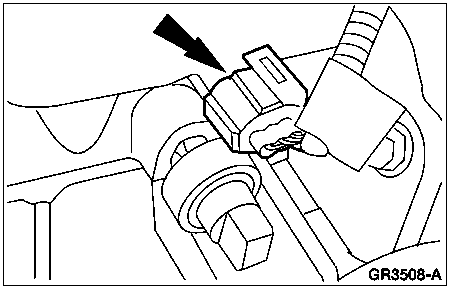
- Disconnect the A/C pressure cut-off switch electrical connector.
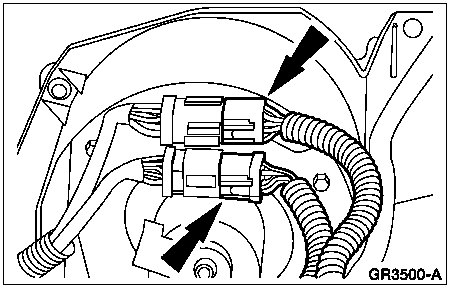
- Disconnect the RH engine compartment in-line wiring harness connectors.
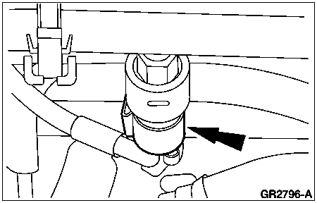
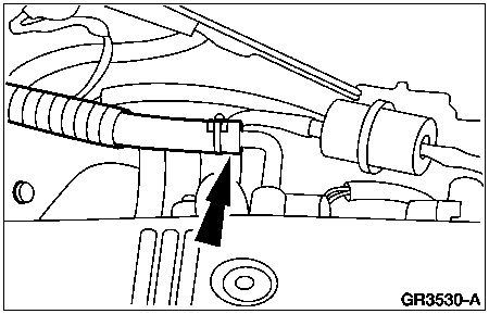
- Disconnect the vacuum line at the intake manifold.
- Disconnect the blower motor controller electrical connector.
- Release the wiring harness locators.
- Remove the RH front wheel and tire assembly. For additional information,
refer to Section 204-04 .
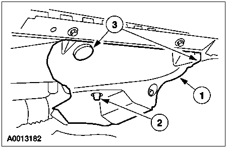
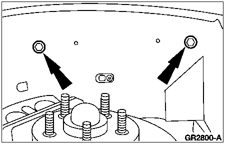
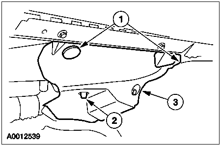
- Remove the upper fender splash shield bolts.
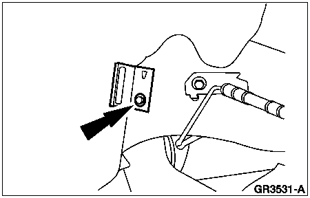
- Remove the lower fender splash shield bolt and locator.
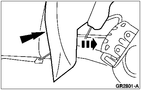
- Position the fender splash shield away from the dash panel.
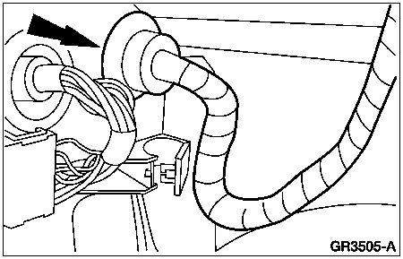
- Unlock the wiring harness guide.
- Unseat the RH wiring harness grommet.
- Install the RH front wheel and tire assembly. For additional information,
refer to Section 204-04 .
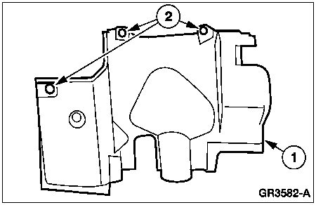
- Remove the RH instrument panel lower insulator.
- Remove the pin-type retainers.
- Release the locking tab.
- Remove the instrument panel lower insulator.
- Disconnect the courtesy lamp.
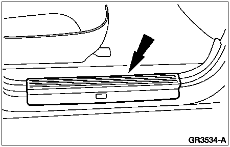
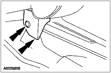
- Remove the LH and RH scuff plates.
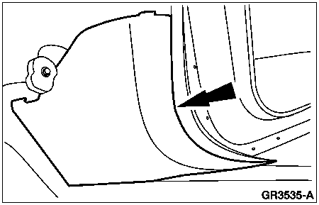
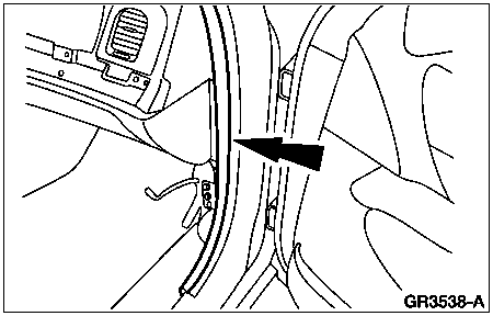
- Remove the LH and RH A-pillar lower trim panels.
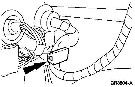
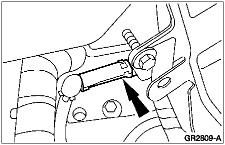
- Disconnect the antenna cable in-line connector.
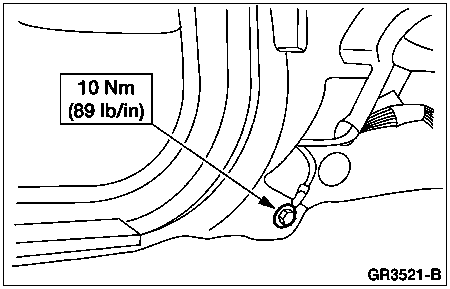
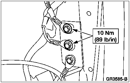
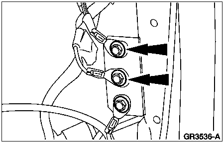
- Remove the RH ground bolts.
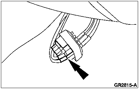
- Disconnect the RH bulkhead electrical connectors.
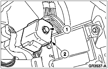
- Loosen the bolt.
- Disconnect the RH bulkhead electrical connectors.
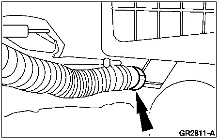
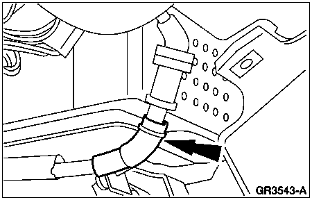
- If equipped, disconnect the electronic automatic temperature control
(EATC) hose from the evaporator housing.
- Position the LH and RH door weatherstrip seals aside.
- Feed the RH wiring harness through the dash panel.
- Disconnect the climate control head vacuum harness connector.
- Remove the pin-type retainer and the instrument panel tunnel brace
cover.
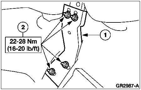
- Remove the instrument panel tunnel brace.
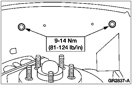
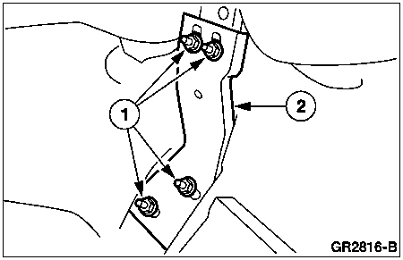
- Remove the nuts.
- Remove the instrument panel tunnel brace.
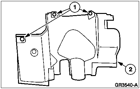
- Remove the LH instrument panel insulator.
- Remove the pin-type retainers.
- Remove the LH instrument panel insulator.
- Disconnect the courtesy lamp.
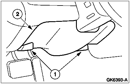
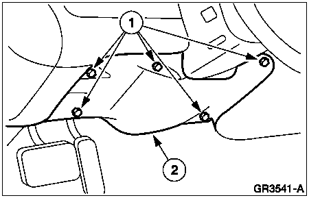
- Remove the instrument panel lower steering column opening cover.
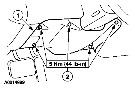
- Remove the screws.
- Remove the instrument panel lower steering column opening cover.
- Remove the instrument panel steering column opening cover reinforcement.
- Remove the bolts.
- Remove the instrument panel steering column opening cover reinforcement.
- Disconnect the parking brake release vacuum connector.
- Disconnect the vacuum connector.
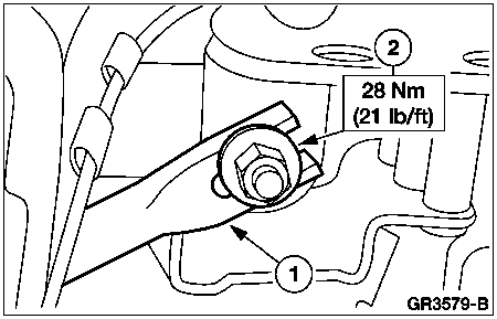
- Position the steering column brace aside.
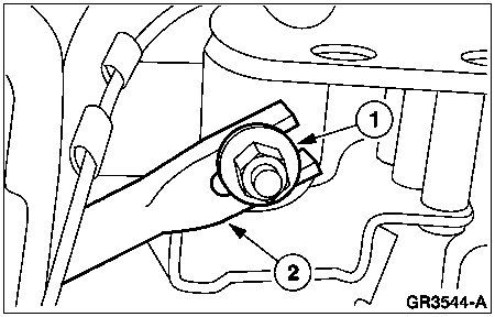
- Remove the nut.
- Position the steering column brace aside.
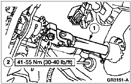
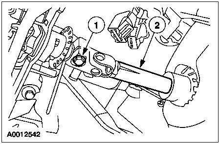
- Separate the intermediate shaft from the steering column shaft.
- Remove and discard the pinch bolt.
- Separate the intermediate shaft from the steering column shaft.
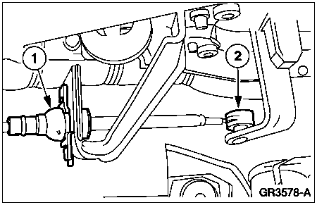
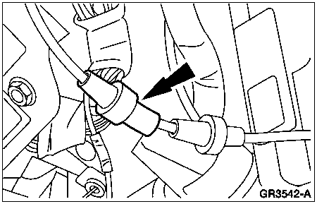
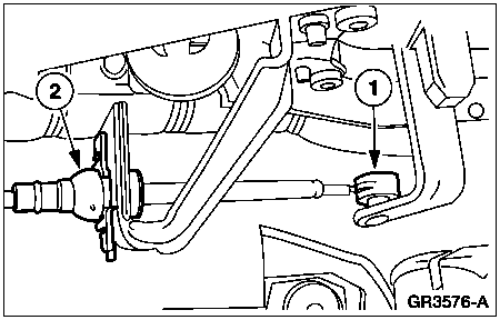
- If equipped, disconnect the transmission shift cable from the
steering column.
- Disconnect the cable from the steering column shift tube lever.
- Disconnect the cable from the steering column bracket.
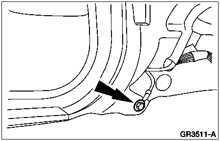
- Remove the LH ground bolt.
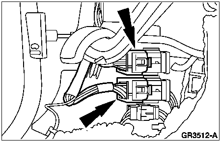
- Disconnect the LH wiring harness connectors.
- Remove the defroster opening grille.
- If equipped, disconnect the electrical connectors.
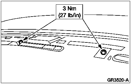
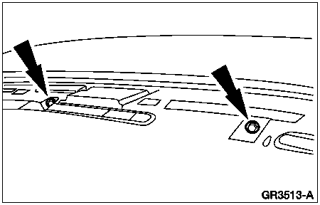
- Remove the three instrument panel cowl top screws.
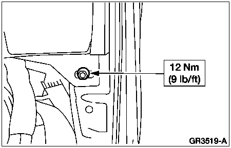
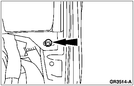
- Remove the RH instrument panel cowl side nut.
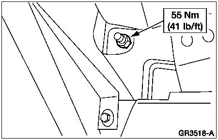
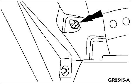
- Remove the upper LH instrument panel cowl side nut.
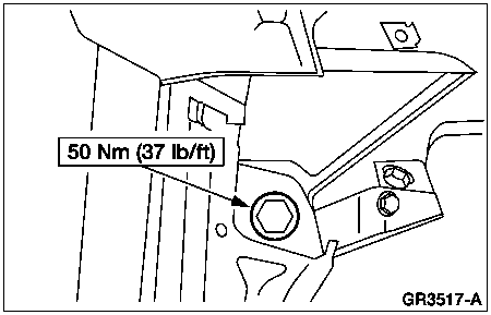
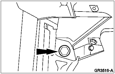
- Remove the lower LH instrument panel cowl side bolt.
-
NOTE: Two technicians are needed to carry out this step.
NOTE: Feed the LH wiring harness through the dash panel while
carrying out this step.
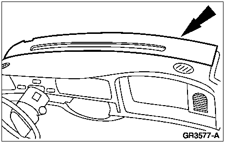
Remove the instrument panel from the vehicle.
Installation
 CAUTION: Electronic modules are sensitive to static electrical charges.
Avoid exposing any modules to static electrical charges, as this may cause
damage to the modules.
-
NOTE: Two technicians are needed to carry out this step.
NOTE: Feed the LH wiring harness through the dash panel while
carrying out this step.
Install the instrument panel into the vehicle.
- Install the lower LH instrument panel cowl side bolt.
- Install the upper LH instrument panel cowl side nut.
- Install the RH instrument panel cowl side nut.
- Install the three instrument panel cowl top screws.
- Install the defroster opening grille.
- If equipped, connect the electrical connectors.
- Connect the LH wiring harness connectors.
- Install the LH ground bolt.
- If equipped, connect the transmission shift cable to the steering
column.
- Connect the cable to the steering column bracket.
- Connect the cable to the steering column shift tube lever.
- Connect the intermediate shaft to the steering column shaft.
- Connect the intermediate shaft to the steering column shaft.
- Install a new pinch bolt.
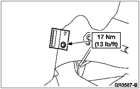
- Install the steering column brace.
- Position the steering column brace.
- Install the nut.
- Connect the vacuum connector.
- Connect the parking brake release vacuum connector.
- Install the instrument panel steering column opening cover reinforcement.
- Position the instrument panel steering column opening cover
reinforcement.
- Install the bolts.
- Install the instrument panel lower steering column cover.
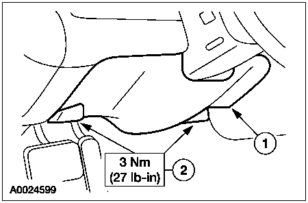
- Position the instrument panel lower steering column cover.
- Install the screws.
- Install the LH instrument panel insulator.
- Position the LH instrument panel insulator.
- Install the pin-type retainers.
- Connect the courtesy lamp.
- Install the instrument panel tunnel brace.
- Position the instrument panel tunnel brace.
- Install the nuts.
- Position the instrument panel tunnel brace cover and install the
pin-type retainer.
- Connect the climate control head vacuum harness connector.
- Feed the RH wiring harness through the dash panel and seat the
wiring grommet.
- Install the LH and RH door weatherstrip seals.
- If equipped, connect the EATC hose to the evaporator housing.
- Connect the RH bulkhead electrical connector.
- Connect the RH bulkhead electrical connector.
- Tighten the bolt.
- Install the RH ground bolts.
- Connect the antenna cable in-line connector.
- Install the LH and RH A-pillar lower trim panels.
- Install the LH and RH scuff plates.
- Install the RH instrument panel lower insulator.
- Position the RH instrument panel lower insulator.
- Engage the locking tab.
- Install the pin-type retainers.
- Connect the courtesy lamp.
- Remove the RH front wheel and tire assembly. For additional information,
refer to Section 204-04 .
- Lock the RH wiring harness into the guide.
- Install the upper fender splash shield.
- Install the lower fender splash shield locator and bolt.
- Install the RH front wheel and tire assembly. For additional information,
refer to Section 204-04 .
- Connect the blower motor controller electrical connector.
- Engage the wiring harness locators.
- Connect the vacuum line to the intake manifold.
- Connect the RH engine compartment in-line wiring harness connectors.
- Connect the A/C pressure cut-off switch electrical connector.
- Connect the blower motor electrical connector.
- Seat the LH wiring harness grommet.
- Connect the LH engine compartment in-line electrical connectors.
- Connect the windshield wiper motor electrical connector.
- Engage the wiring harness locators.
- Connect the brake fluid sensor electrical connector.
- Connect the LH engine compartment in-line electrical connector.
- Engage the wiring harness locators.
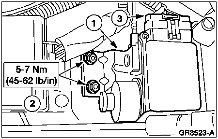
- Install the speed control servo.
- Position the speed control servo.
- Install the nuts.
- Connect the electrical connector.
- If equipped, install the floor console. For additional information,
refer to Floor Console in this section.
- Install the driver air bag module. For additional information,
refer to Section 501-20B .
- Install the passenger air bag module. For additional information,
refer to Section 501-20B .
![]() CAUTION: Electronic modules are sensitive to static electrical charges.
Avoid exposing any modules to static electrical charges, as this may cause
damage to the modules.
CAUTION: Electronic modules are sensitive to static electrical charges.
Avoid exposing any modules to static electrical charges, as this may cause
damage to the modules. 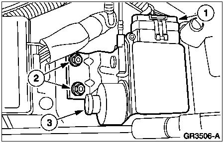