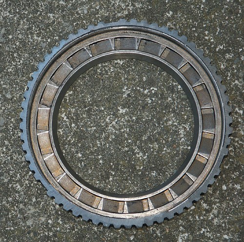
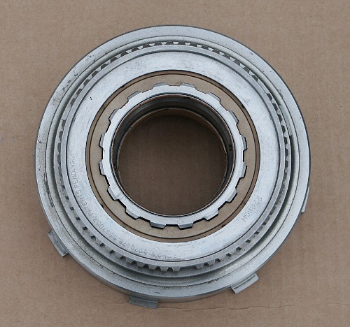
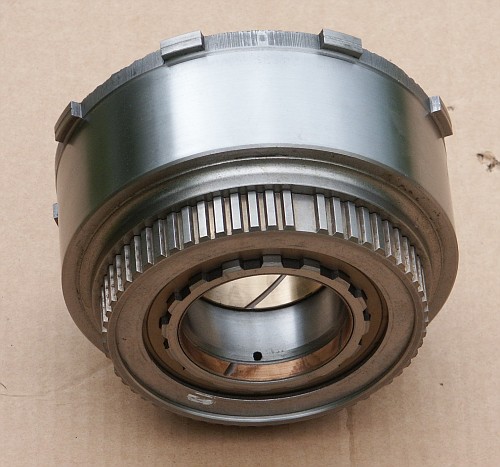
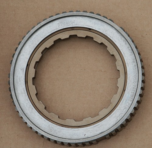
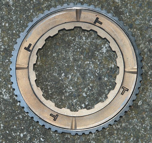
Here are some pictures of the mechanical diode setup used in the ford
4R70W and 4R100 transmissions.
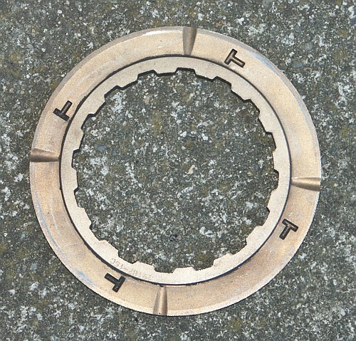
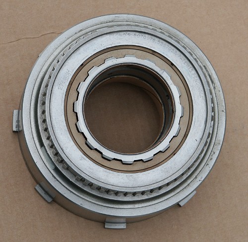
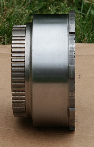
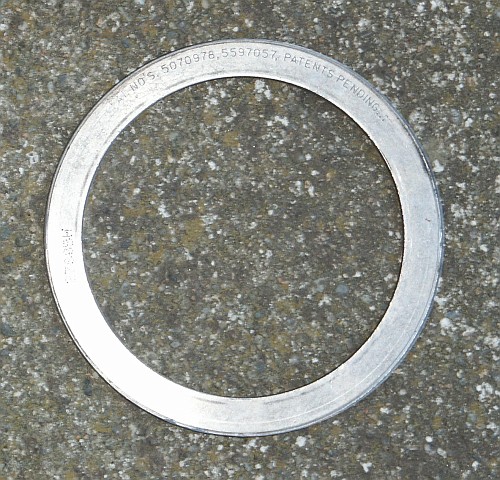
You can view the patent's referenced in the numerical stampings on the
front of the mechanical diode by clicking here.
This device makes a neat sounding ratchet sound when the clutch is
over-running. And locks up in the other direction. When actually
installed in a transmission with shafts spinning at hundreds of
revolutions per minute, this device would be coated in a layer of oil
and would be silent when over-running though.

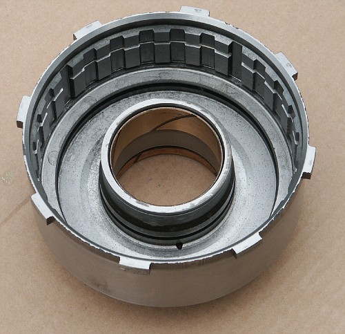
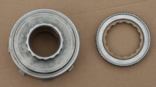
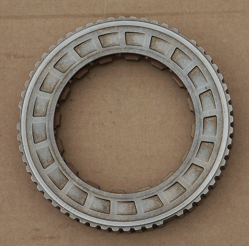
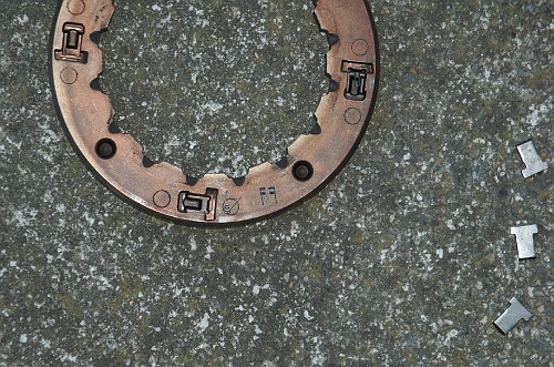
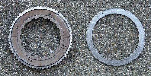
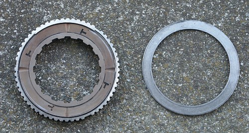
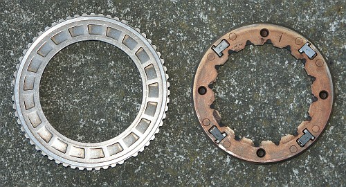
Here's the clutch assembly after grinding away the retaining ring. This
stuff is really hard metal that takes some effort to cut through.
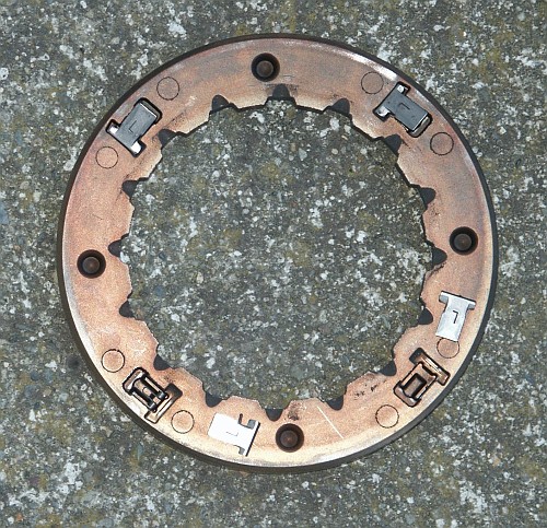
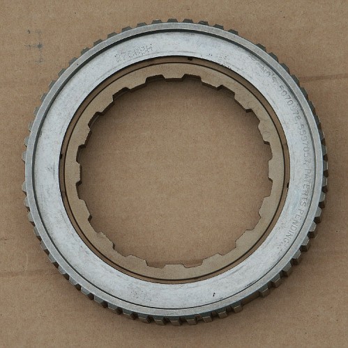
After popping off the top ring
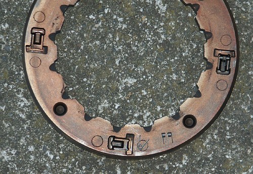
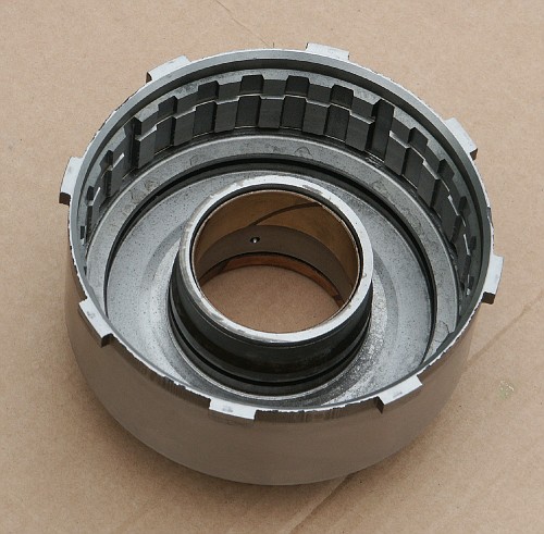
The front of the top ring
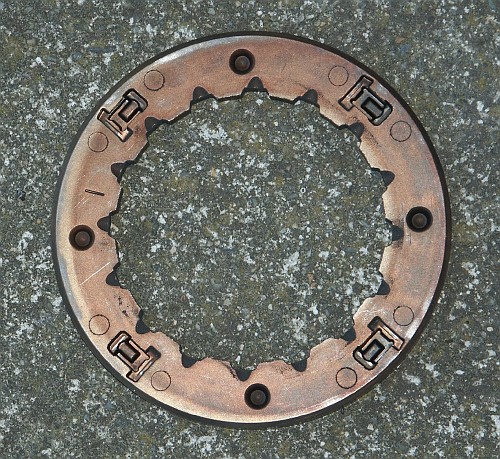
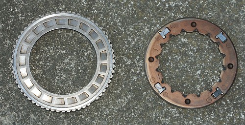
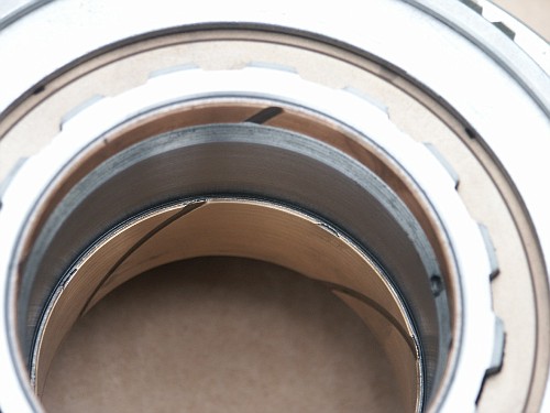
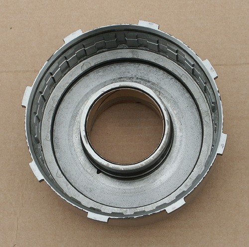
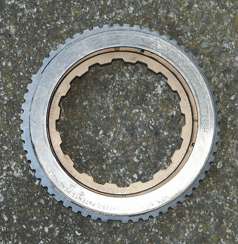
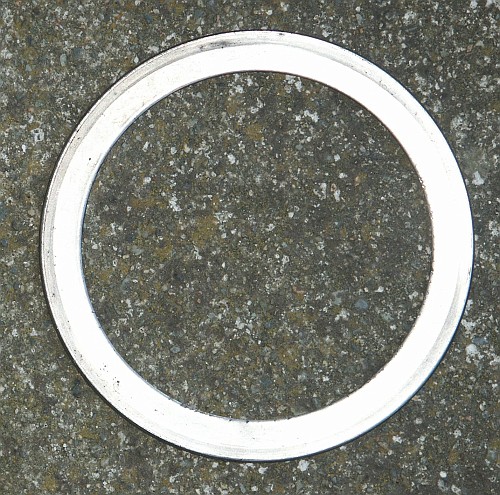
The back of the top ring
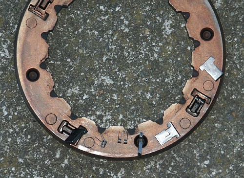
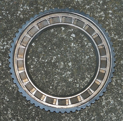
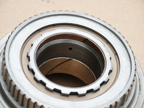
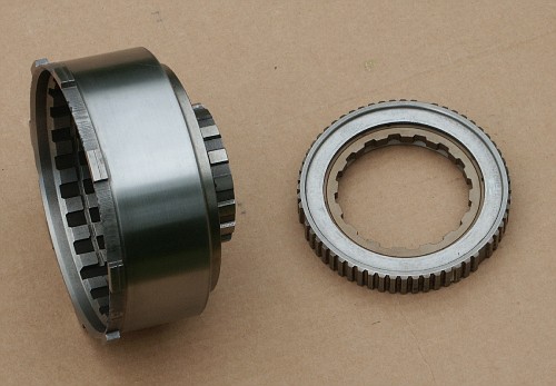
Here's the inside of the clutch. The metal tangs are spring loaded.
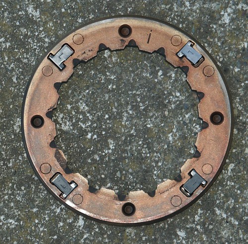
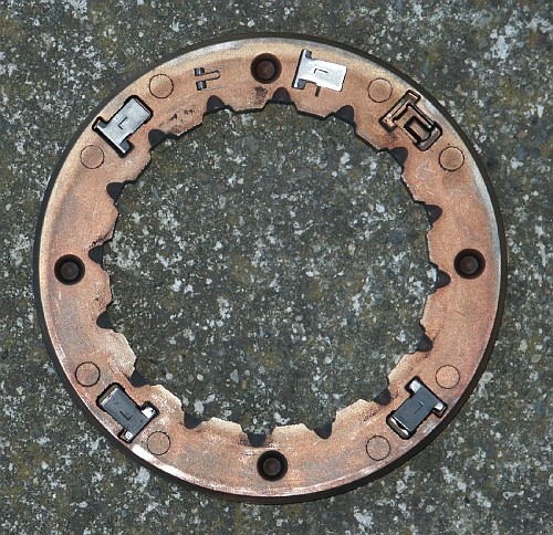
Here you can see a closeup of one of the springs
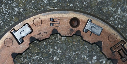
This is the surface that the tangs would normally lock onto