A few crown vic owners have reported the turn signals flashing very fast
at random points in time when the climate control unit fan speed is set
on "high". Is typically no set pattern to the behaviour, but it appears
to occur at the greatest frequency when the vehicle is driven in stop and
go traffic. I had seen this behaviour on my 98' police interceptor a couple
times, but after replacing the wornout blower motor the problem started
occuring almost every time I drove the vehicle and had the blower motor
set on high. Further investigation revealed that I was getting close to
a 2V voltage drop between the alternator output stud and some of the devices
inside the car after the ignition switch when the blower motor was set on
high.
Suspecting that the erratic turn signals were caused by too low of a
voltage getting the multifunction switch and other ignition switched components,
I decided to rewire my vehicle to test the theory. My police interceptor
has two police power leads, one always hot, the other hot when the key is
in the run or acc positions. First I removed the climate control head from
the dash, then cut the BR/O wire in two on the back. Took one of the coil
wires of a generic 30amp SPST relay and hooked it to ground, hooked the other
coil wire to the BR/O wire coming out of the dash harness. Connected one
terminal of the relay contacts to the constant hot police power lead and
the other to the BR/O wire that ran into the climate control head.
Had now reduced the load for the blower motor that flows through the ignition
switch from over 20Amps to around 0.2Amps. Turn signals behave normally now.
The sporadic problem of only the left turn signal indicator, not the right
flashing when I engaged the hazard flashers had also corrected itself.
Keep in mind that the blower motor relay will get a warm when the blower
motor is running for extended periods due to the large amount of current
passing over relatively small resistive relay contacts. So choose your mounting
location accordingly.
Later I read TSB 01-21-3 and saw that ford
had issued a technical service bulletin to correct the fast flash rate
problem on 1998-2000 crown victorias. The first few steps were to remove
the underdash trim panels and lower the fuse panel from the dash. Then
locate and "cut circuit 298 Violet/Orange wire 4 inches from bottom of steering
column shroud".
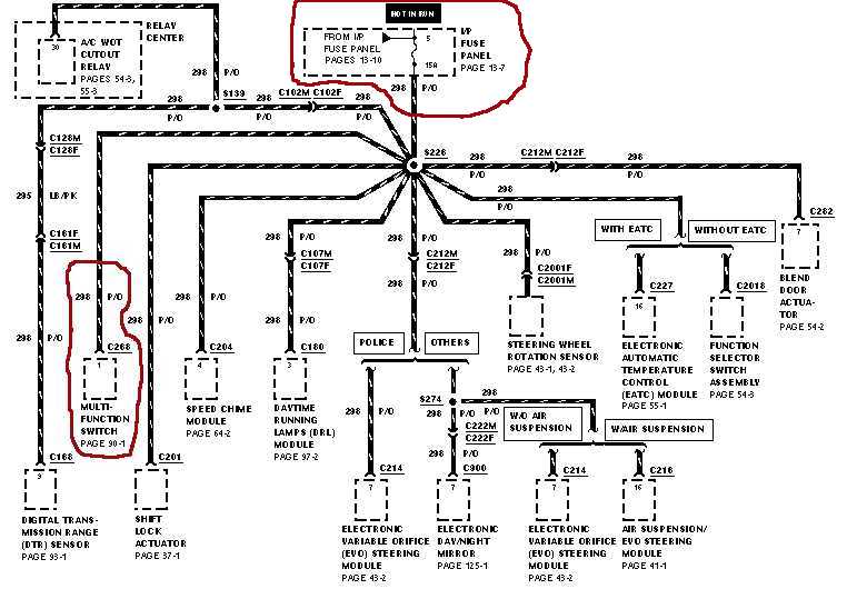
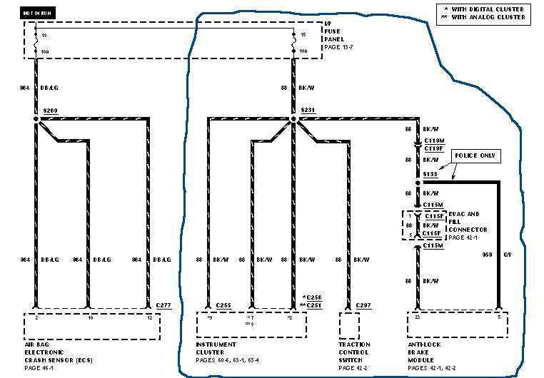
As can be seen in the diagrams below, the P/O (purple with orange stripe)
wire in circuit 298 supplies power to the multifunction switch.
Note that violet and purple refer to the same color and are used interchangeably
in this document.
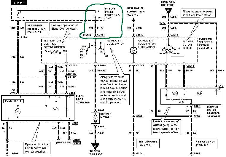
Also on the GY/Y branch of the ignition switch circuit is the blower
motor for the climate control system.
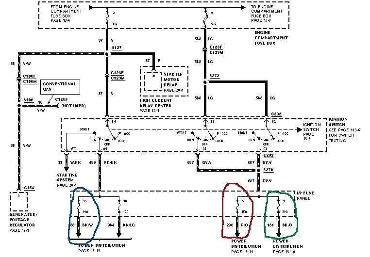
Note that in the above diagram and in actual implementation in the vehicle,
two seperate sets of contacts are wired in parallel inside the ignition
switch to feed the GY/Y branch of the ignition switch socket. This is presumably
done to minimize resistance and the resulting voltage drop on this circuit.
Next step in the TSB was to "locate circuit 88 Black/White wire located
in fuse cavity #15". Then "splice jumper wire to fuse 15 wire", and "splice
[the other end of the] jumper wire to [the steering] column wire". What
the above steps are effectively accomplishing is removing the multifunction
switch from the branch of the ignition switch harness that also feeds the
blower motor and placing it on the branch of the ignition switch harness
that feeds the antilock brake module and the instrument cluster. As mentioned
previously, the blower motor consumes massive amounts of power when set
on the "high" speed which causes lower than normal voltage to supplied to
the rest of the components on the GY/Y branch of the ignition switch circuit.
If a lower than normal voltage is supplied to the lcm through the multifunction
switch, then current flow through the turn signals bulbs will also be lower
than normal and the lcm will incorrectly assume that a bulb has burned out.
When the lcm thinks that a bulb has failed, it will flash the offending turn
signal at a fast rate to indicate the problem to the vehicle operator.
The circuit that the TSB suggests the multifunction switch power feed
be moved to has a relatively stable voltage present on it since there are
no high draw components connected to the BK/W or DB/LG wires. The airbag
system draws negligible current during normal vehicle operation. The instrument
cluster has some low draw warning lights and guages on it and the ignition
switched power leads for the antilock brake module are just sense wires.
Curiously, starting in the 2003 model year, crown vics became factory equipped
with a blower motor relay that reduces the load the blower motor puts on
the ignition switch to negligible amounts.
Alternatively, some people have reported successfully restoring a normal
blinking rate to their turn signals by wiring another turn signal bulb and
socket in parallel with one of the existing bulbs.
Three different solutions to the fast flash rate problem are presented
above. The first leaves the multifunction switch on it's original circuit
but removes the blower motor power feed which in turn stabilizes voltage
supplied to the multifunction switch. The second solution leaves the blower
motor on it's original circuit but moves the multifunction switch to a circuit
with a more stabile voltage on it. The third solution lowers the overall
impedance of the turn signal bulb circuit, so even if a lower than normal
voltage is present, a sufficent amount of current will still flow to prevent
the lcm from incorrectly assuming that a bulb has burned out.
Additionally, two other solutions to the fast blink rate problem have
not been covered above. There is a new revision of the lighting control module
that allows a lower amount of current to flow through the turn signal circuit
before it will flash the bulbs fast to indicate a bulb has failed. Also,
the lcm can be removed entirely from the turn signal circuit and a seperate
external flasher module wired in it's place.