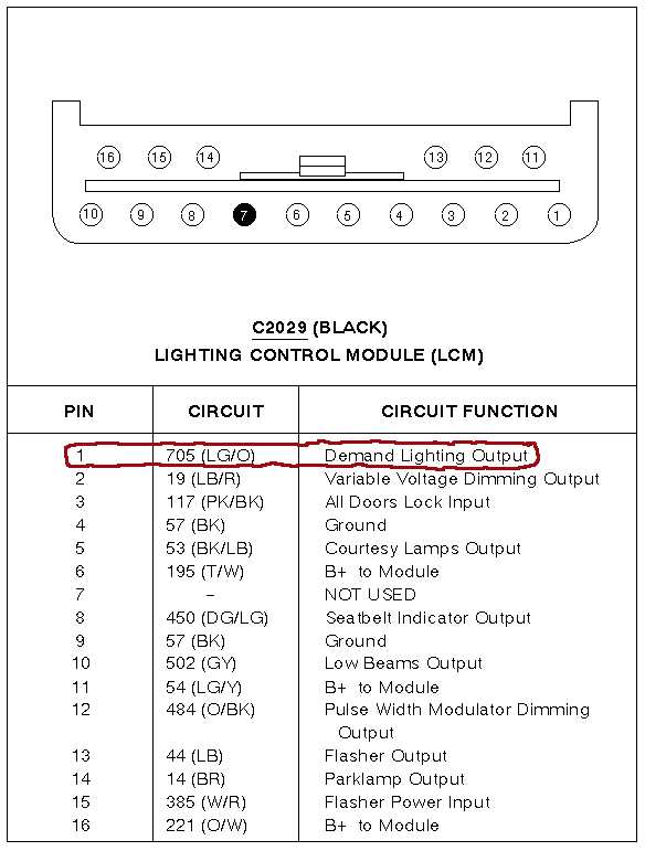
| Pin |
Function |
| 1 |
Ground |
| 6 |
Ignition switched +12V source (Demand Lighting) |
| 4 |
Outputs +12V whenever the light sensor
senses low light conditions |
| 2 & 3 |
Connected to the light emitting diode (LED)
inside the sensor. On civilian models, this led flashes as a visual theft
deterrent and also indicates if the PATS system is functioning properly.
But police models do not have a pats controller, so the wires can be
left disconnected or if you've got an aftermarket alarm they could be
connected to the alarm. |

| Pin |
Function |
| 1 |
Ignition switched +12V source (Demand Lighting) |
| 2 |
Ground |
| 3 |
Outputs +12V whenever the light sensor
senses low light conditions. |
| 4 |
Not Used |
| 5 |
Not Used |
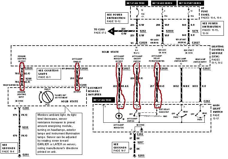
| Pin |
Function |
| 1 |
Power in Start and Run |
| 2 |
To autolamp on/off switch (provides a ground path
when autolamps are enabled by the vehicle operator) |
| 3 |
Outputs +12V to the headlamp & parking light
relay coils during low light conditions |
| 4 |
Constant +12V |
| 5 |
To headlight delayed exit adjustment on headlight
switch (controls amount of time headlights stay on after ignition is turned
off) |