Below are some notes about installing a 200 amp mitsubishi alternator
from a 2009 ford crown victoria police interceptor into a 1998 crownvic
that originally came with a 135amp ford 6G alternator.
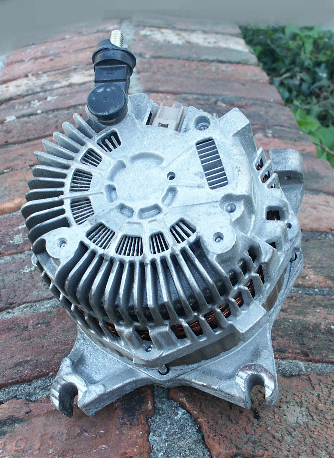
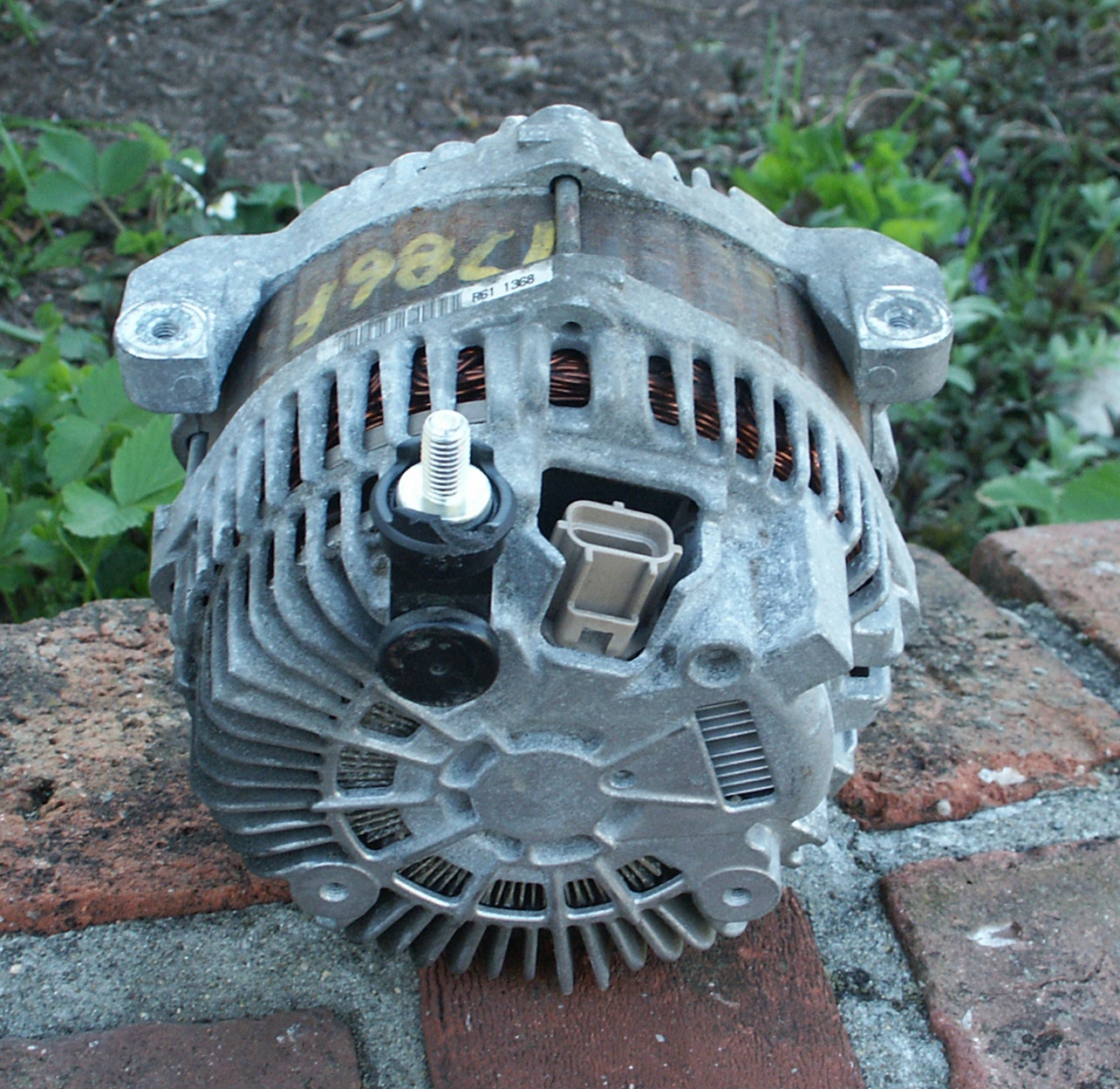
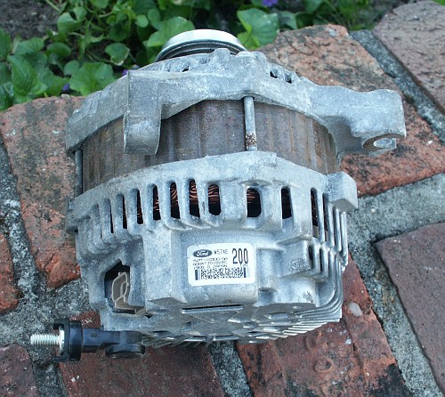
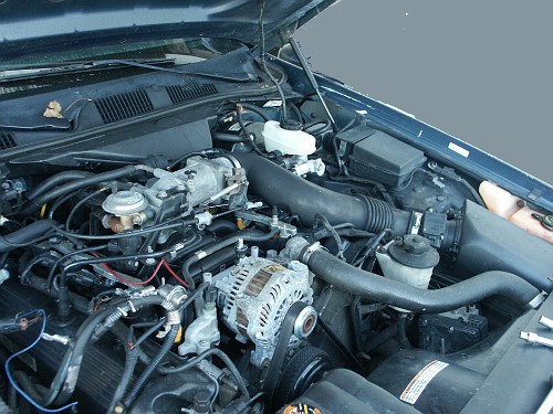
Here's the alternator we want to upgrade to.
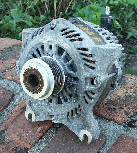

This unit has about 10k miles on it and was in use for about a year
before the car was wrecked.
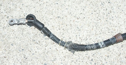
In the northeastern united states, large quantities of chloride road
salts are applied to the roads during the winter to melt
snow and ice. And this how an alternator looks after just one new
england
winter.

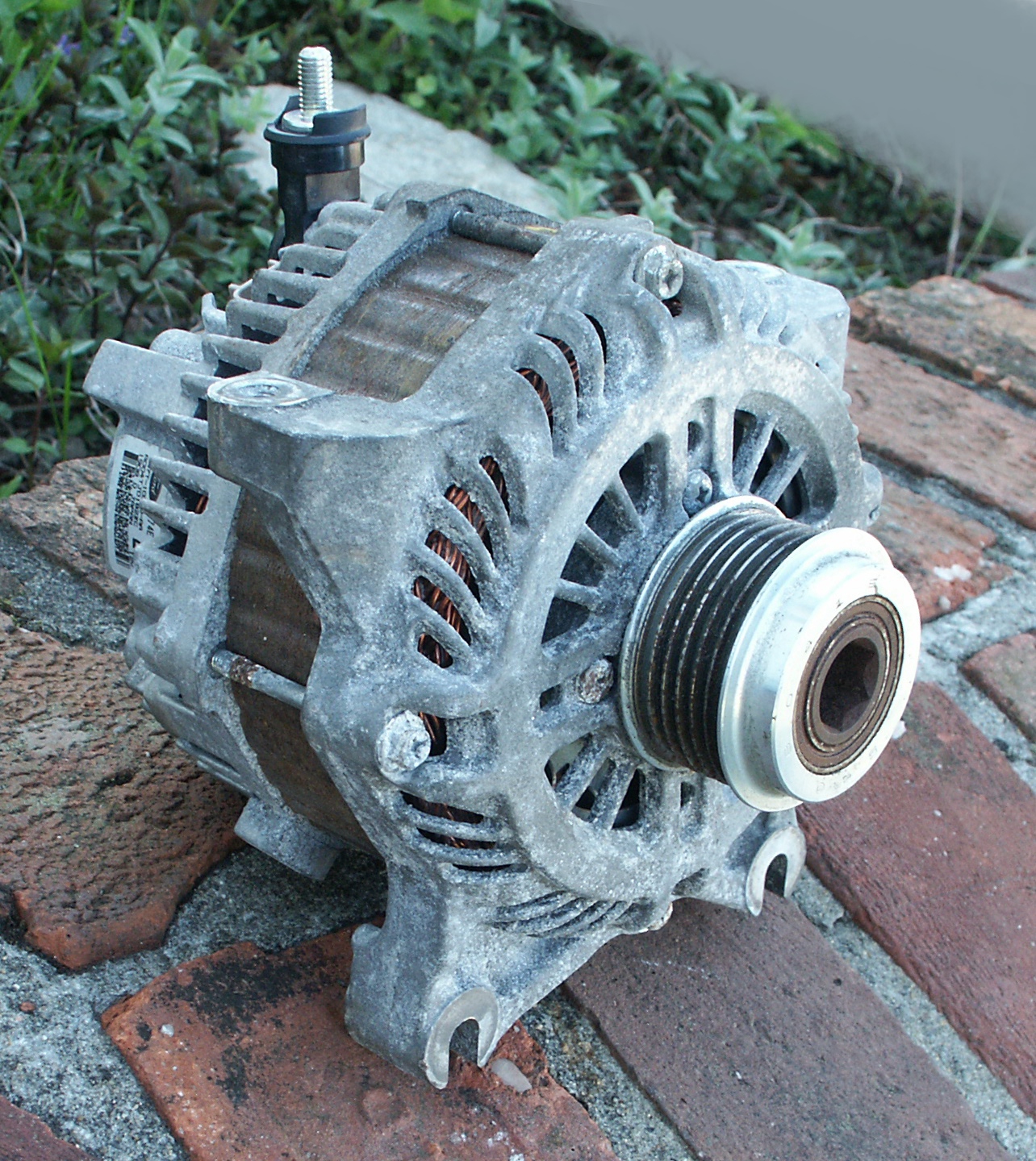
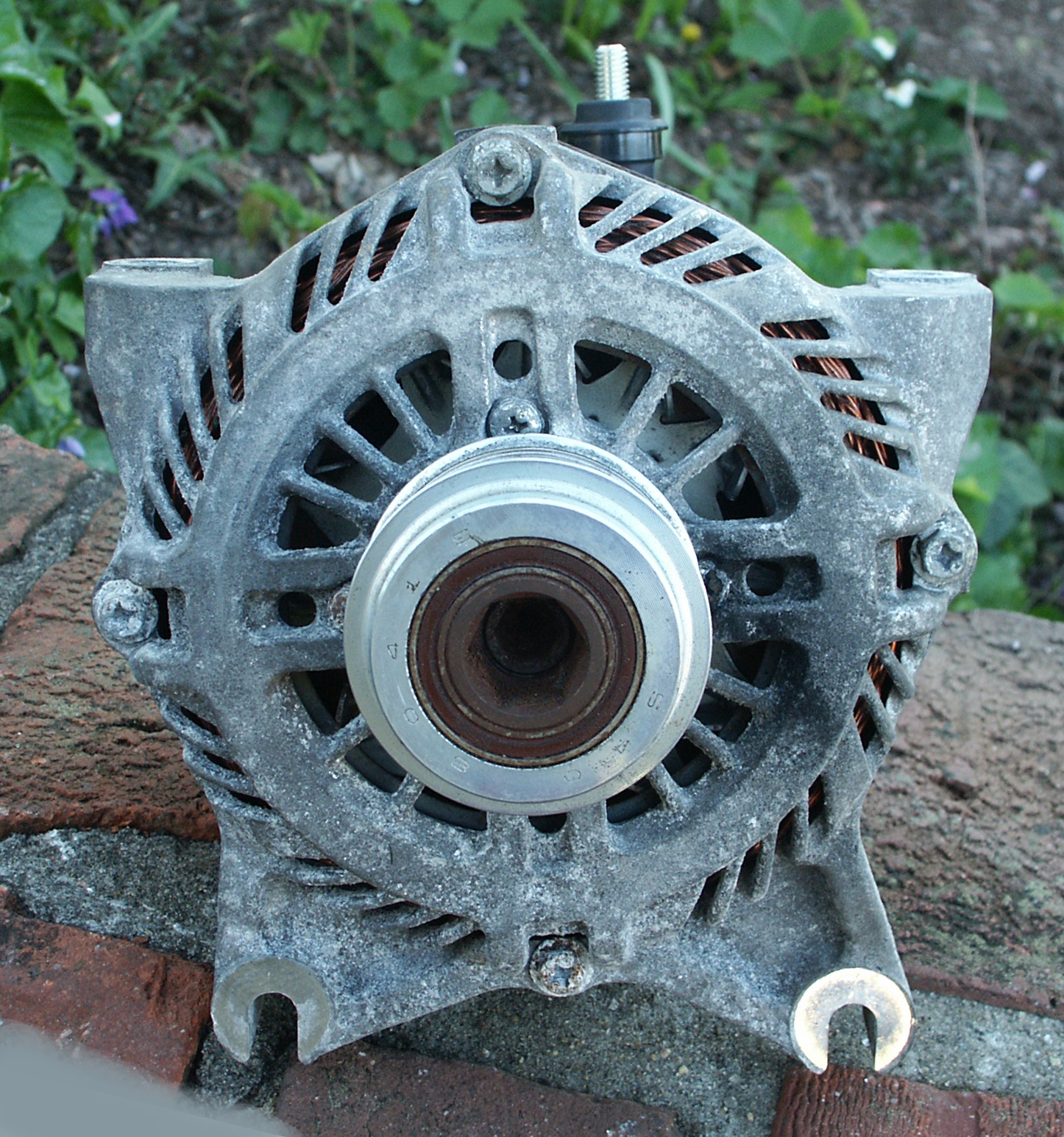
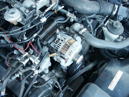
The pulley on this alternator is clutched due to the high rotating mass
of the alternator rotor. The one way clutch locks when rotated
clockwise, but freewheels when rotated in the other direction. When
car's engine is running, the alternator clutch will be locked most of
the time, but it will freewheel during hard acceleration when the
transmission shifts cause abrupt changes in the engine crankshaft
rotation speed. It will also freewheel when the engine is shut off and
the inertia of the heavy rotor keeps the alternator shaft spinning for
a bit. Do note that this is just a "one-way" clutch and not an "overrunning alternator
decoupler" (OAD) pulley like you'll find in some other vehicles.

There is a little surface rust on the pulley because the alternator sat
unused for several months after the car was wrecked. This came right
off after the alternator was installed in a car and run for a couple
hours with the serpentine belt rubbing against the metal.

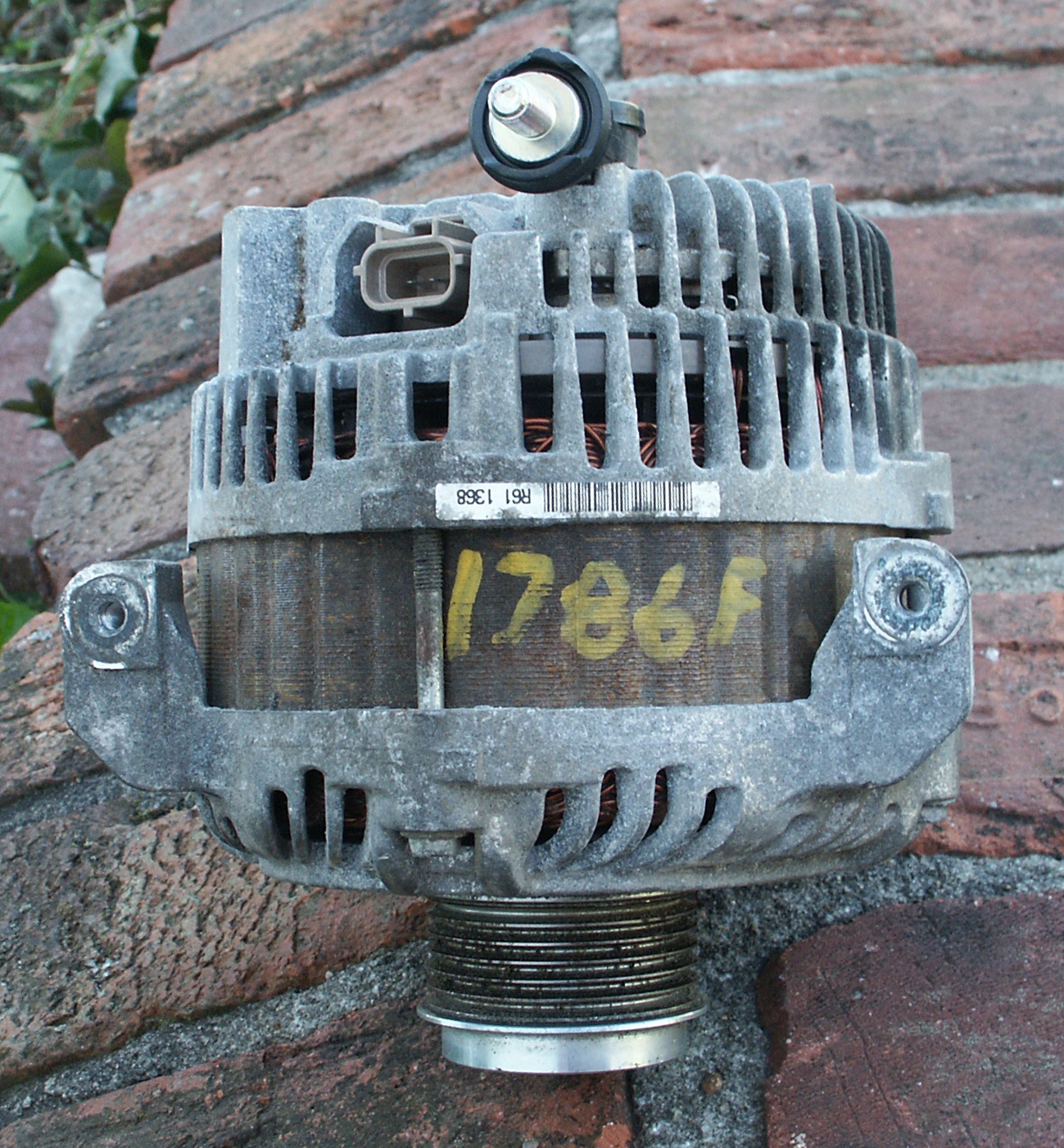
Here is the 200 amp tag on the alternator
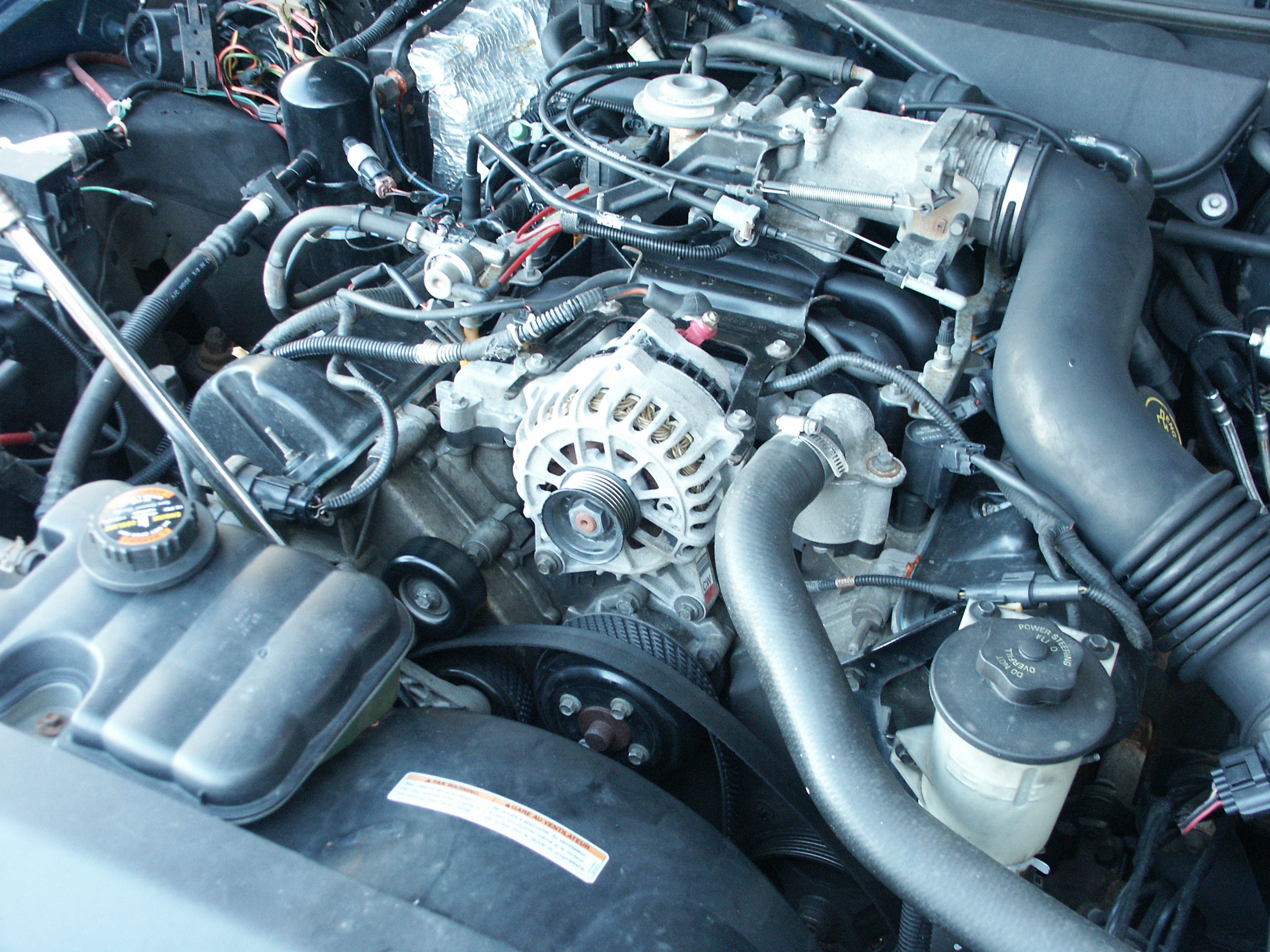
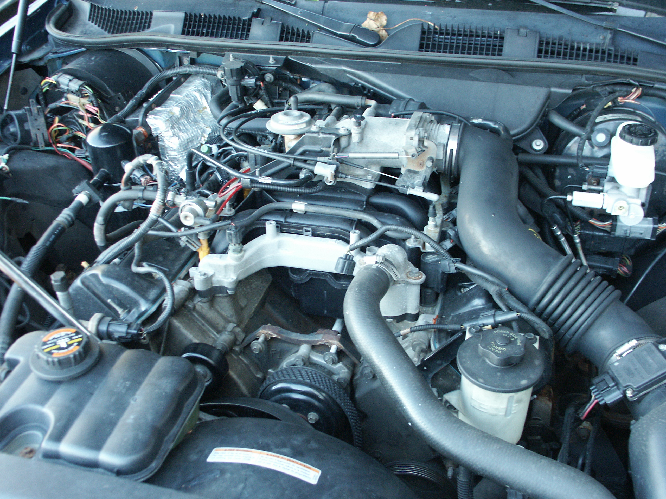
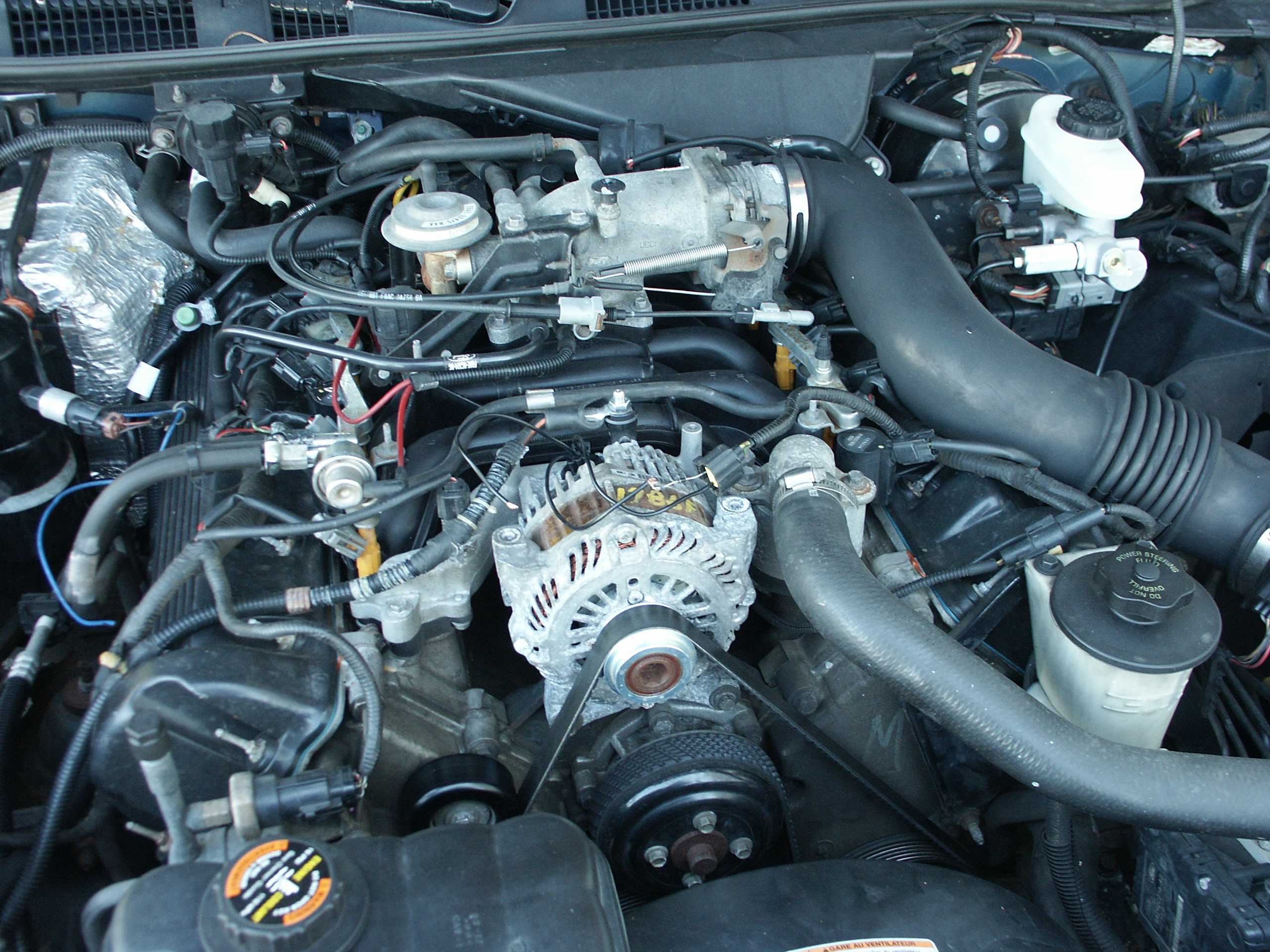
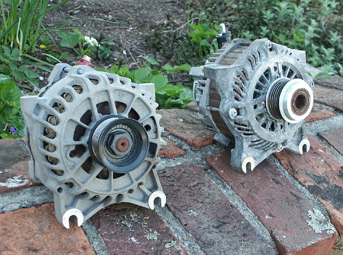
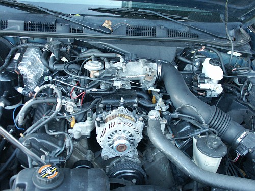
Now let's take a look at the 135amp sixth generation (6G) ford
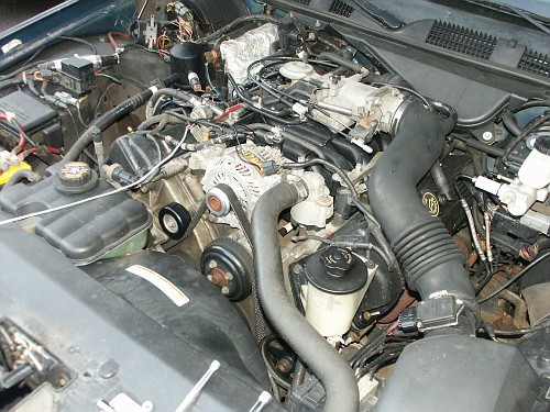
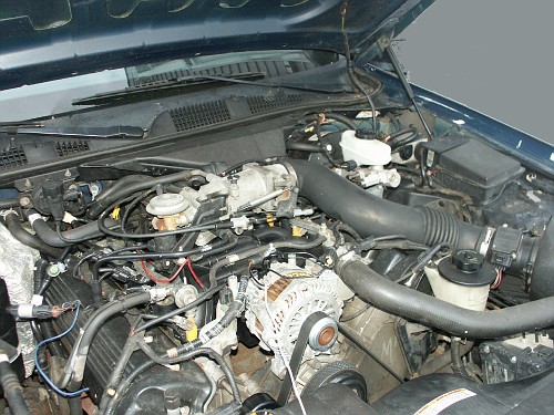
alternator in the 1998 crownvic that we want to upgrade.
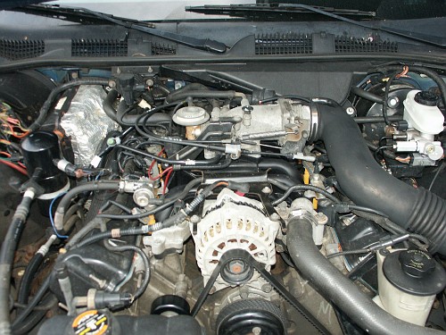
After removing the front engine accessory belt from the alternator

The alternator with the high current charging wire disconnected and the
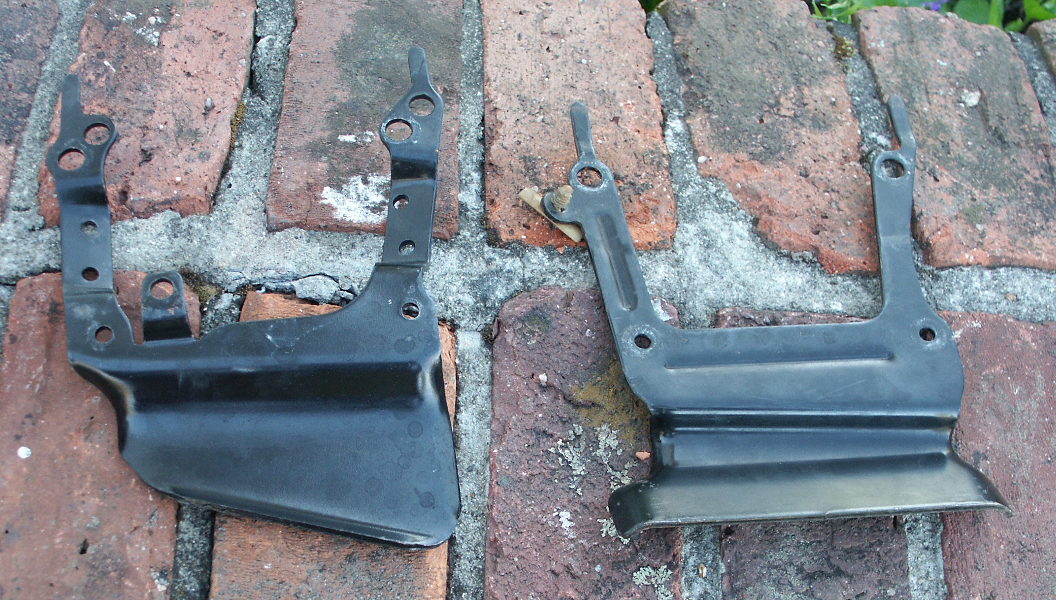
top mounting bracket removed
The alternator top support bracket from the top
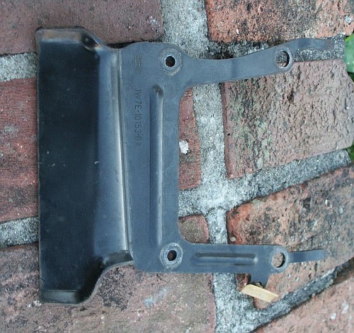
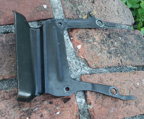
The bracket from the bottom. The raised area in the bracket is to
protect the fuel rail hose during a very high energy frontal collision.
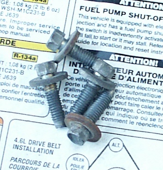
Here are the 4 mounting bolts for the alternator

After loosening the bottom two mounting bolts, unplugging the regulator
connector, and lifting the alternator out

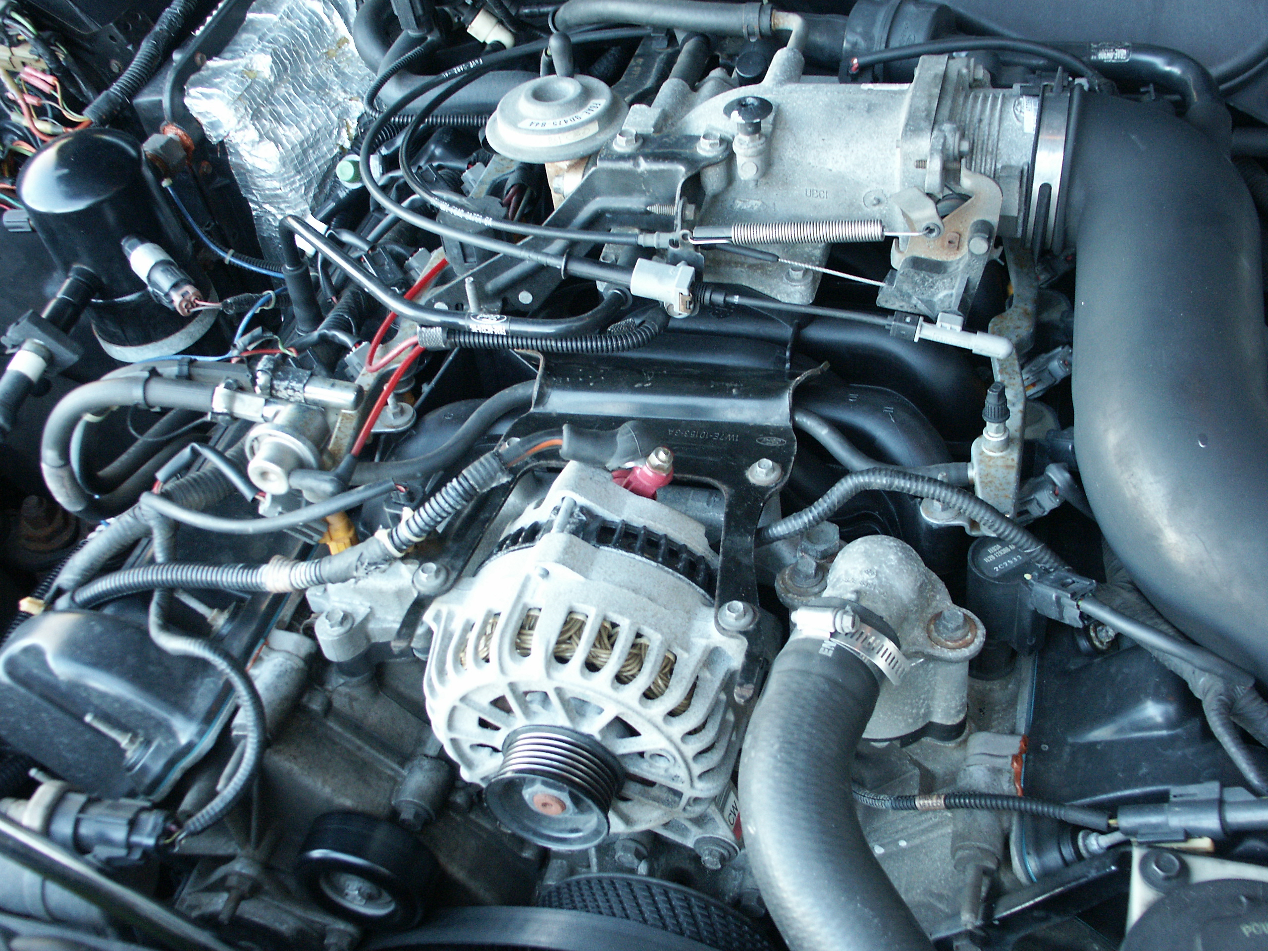
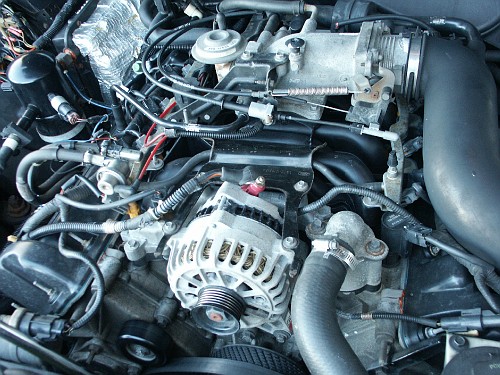
Now that the alternator old alternator is removed, we can try to
install the "new" one.
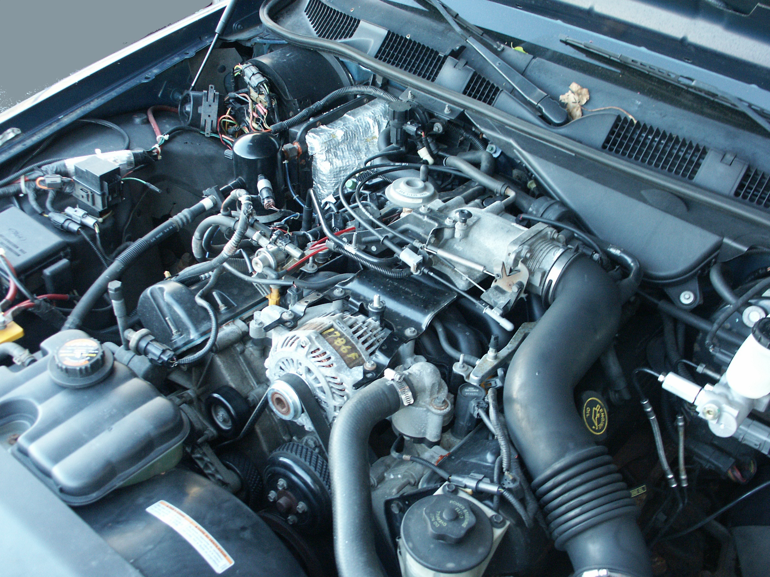
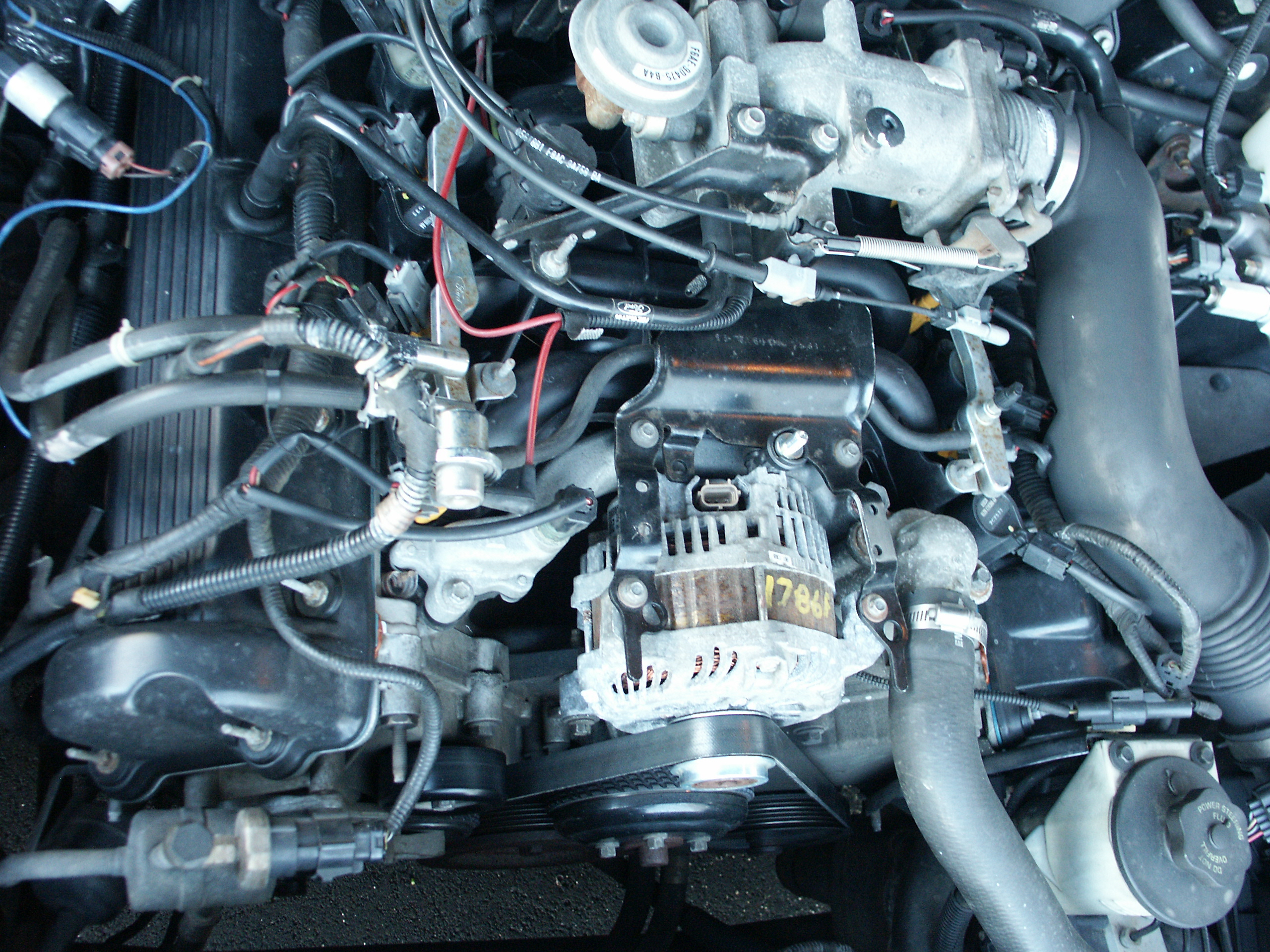
The alternator physically fits on the engine. But, the regulator wiring
is too short to reach the regulator in it's new location due to the
different location of the regulator connectors on the two different
alternators.
Besides the physical length of the regulator wiring, there is also
another hidden issue here of this late model alternator regulator being
controlled with different electrical signals than this earlier model
car generates.
But for now, we are concentrating on the physical fitment issues of the
alternator rather than the electrical control side.
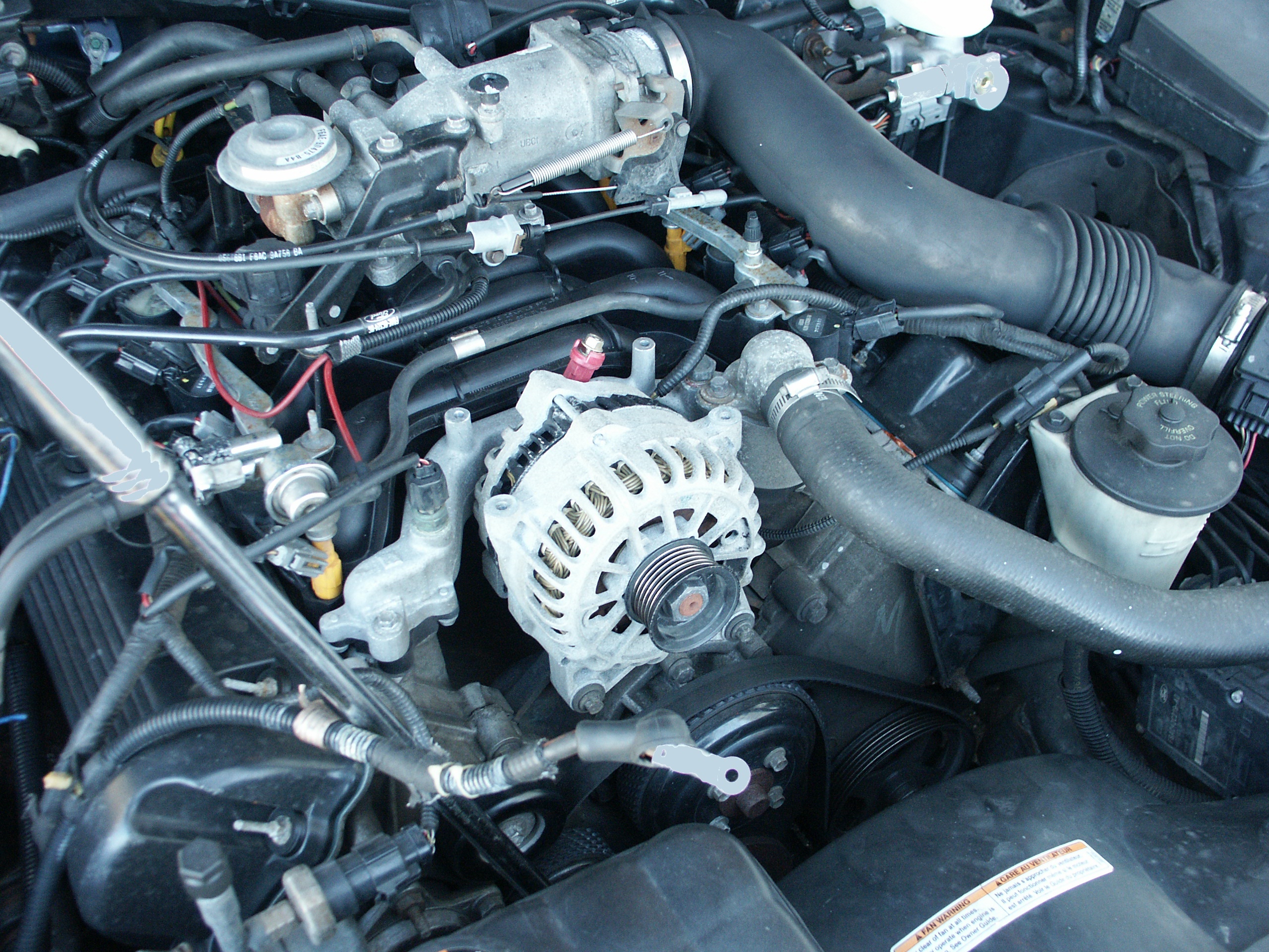
Here are the two alternators side by side. Note the different location
of the regulator connector.


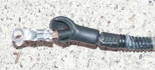
Also, the opening in the ring terminal on the alternator output wire is
too small to fit over the alternator output post stud.


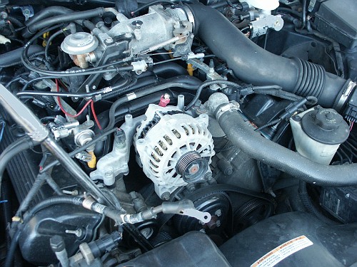
The serpentine belt fits over the alternator pulley without any
modification.
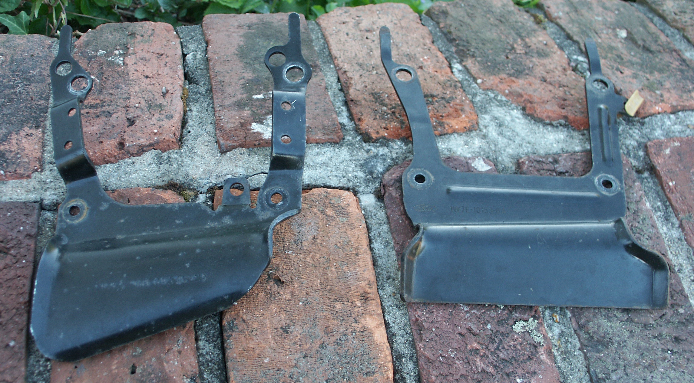
Also, the alternator top mounting bracket does not fit properly with
the new alternator installed. Before the alternator bracket can be slid
so that it's bolt holes line up with the alternator and intake manifold
bolt holes, bracket hits up against the output charging post. A little
work with a 4" angle grinder could likely fix this issue.
Another option is to use the alternator bracket that came with the
dorman intake manifold kit. It's got more space open towards the back
where the alternator output post is located.
The oem ford 6G alternator bracket next to the aftermarket dorman
universal
3G/4G/6G bracket


This is a universal bracket for cars with 3G, 4G and 6G alternators.
The 3g tab on the bracket comes a little close to the alternator,
cutting this unused tab off would open up some space near the regulator.


Now lets remove the alternator output wire and enlarge the ring
terminal with a 5/16" drill bit so that it will fit over the new
alternator
output stud. The old alternator uses a M6x1.0 stud on the output post,
the "new"
alternator uses a M8x1.25 stud instead.
Before modification
After modification
Now that the charging wire hole has been opened up, we can connect the
alternator output wire and begin tinkering with the control aspects of
the new alternator regulator.
This alternator will self excite without any regulator wires connected
at all, but charging voltage will only be 13.6 volts under minimal load
which is too low for good battery recharge characteristics. So we need
to find some way to raise the voltage output of the alternator. My
first idea was to use the alternators no-pcm-communication failsafe
voltage setpoint and insert a diode or two inline
with the voltage
sense
terminal to make the alternator think that the battery voltage was
lower than it actually was.
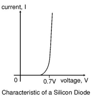
In introductory electrical theory textbooks, you'll read that a
diode always drops 0.7 volts across it. But in the real world, the
voltage drop across a diode varies as a function of current and various
other parameters. This causes the alternator output voltage to float
around some as the car runs and things heat up. At first, i was only
getting around a 0.4V drop across each diode, but later this started to
ramp up close to 0.7V across each.
Maybe some high current diodes like those in a marine battery isolator could have
solved the voltage float problem mentioned above or maybe a voltage
divider consisting of a couple resistors could have been installed
instead. But a cleaner
solution is to send the alternator fake voltage setpoint data on the
gencom line. This way, the alternator will think that it's installed in
an actual car recieving voltage setpoint requests from the powertrain
control module (PCM).
The 2003 and later crownvic alternators have a PCM controlled
alternator regulator. There are two unidirectional control lines going
to the regulator. The gencom line has information on it about what
voltage the alternator should output. And the genmon line has
information about what load the alternator is under, any problems the
alternator may have, and various other operational data.

Unfortunetly, the 2002 and earlier crownvics control their alternators
differently. The voltage setpoint inside the regulator is fixed and
non-adjustable. And rotor field coil excitation voltage is obtained
through the instrument cluster i-line to tell the alternator when to
turn on/off the rotor magnetic field.

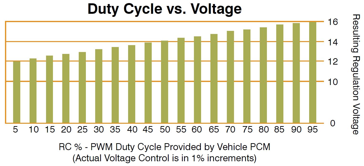
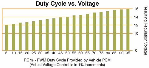
But if we place a 125Hz pulse width
modulated (PWM) square-wave signal on the alternator gencom line of
our "new" alternator, we can vary
the alternator voltage setpoint by changing the duty cycle of the
waveform.
A search for pwm circuit ideas revealed that there are a number of
premade pwm circuits on the market catering to the HHO hydrogen generation crowd. The
idea is that you can extract hydrogen from water which can then be fed
through an automobile's engine air intake system to increase fuel
economy. Many of these circuits were originally intended to control the
speed of electric motors, but we can retask them for our alternator
control project if they have an output frequency close to 125 Hertz and
they are designed to control motor speed through the ground side of the
circuit.
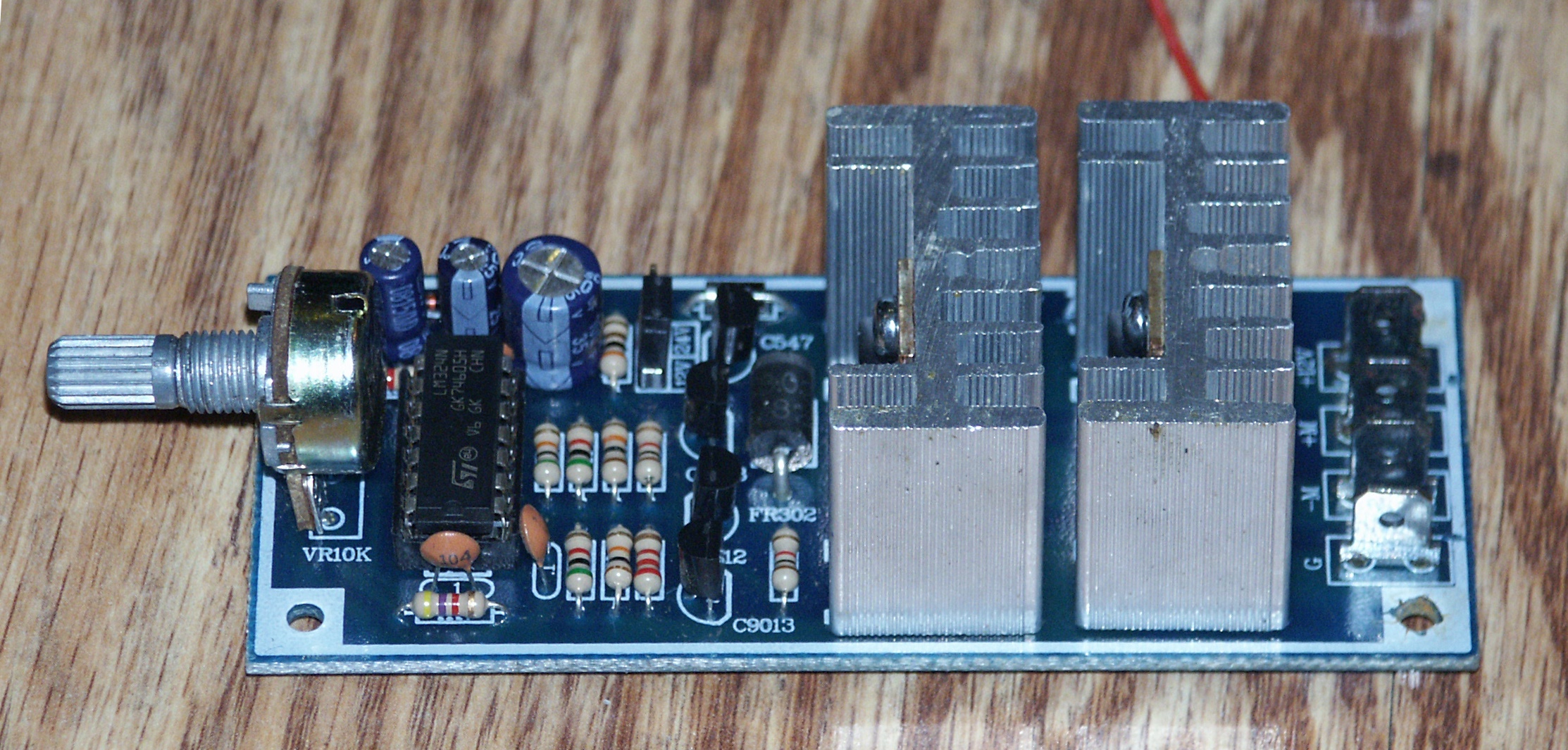
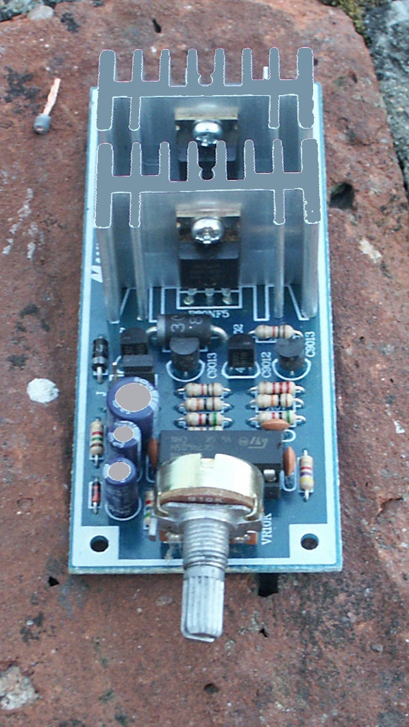
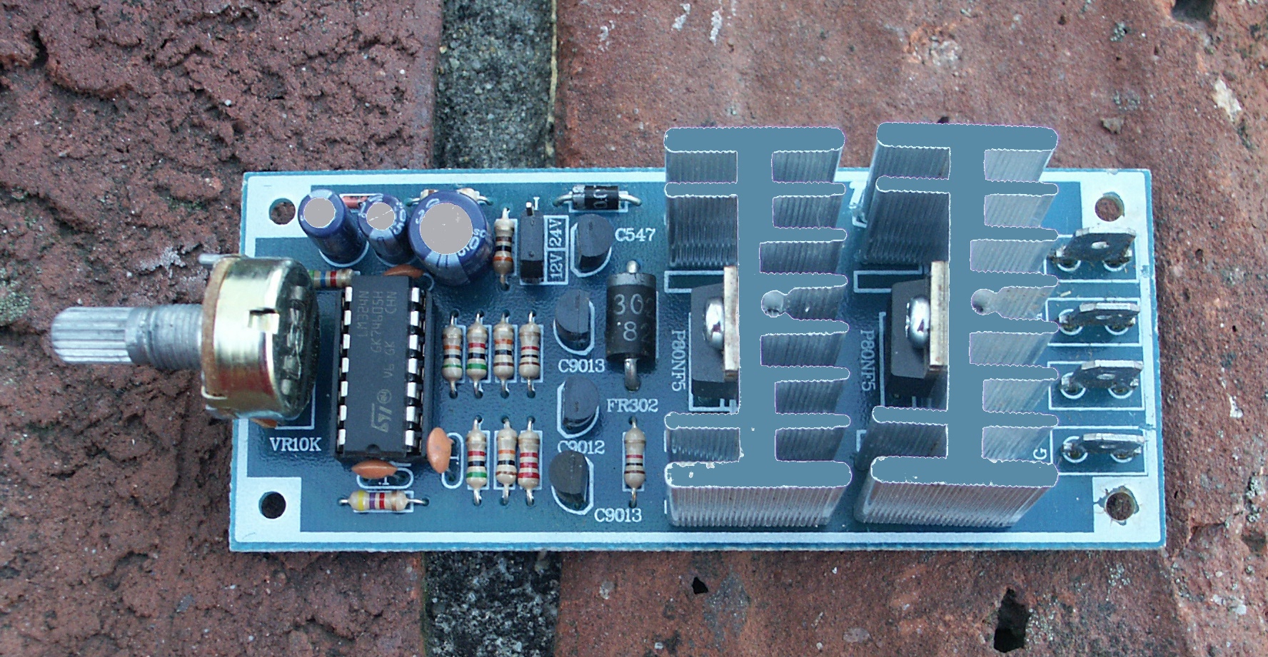
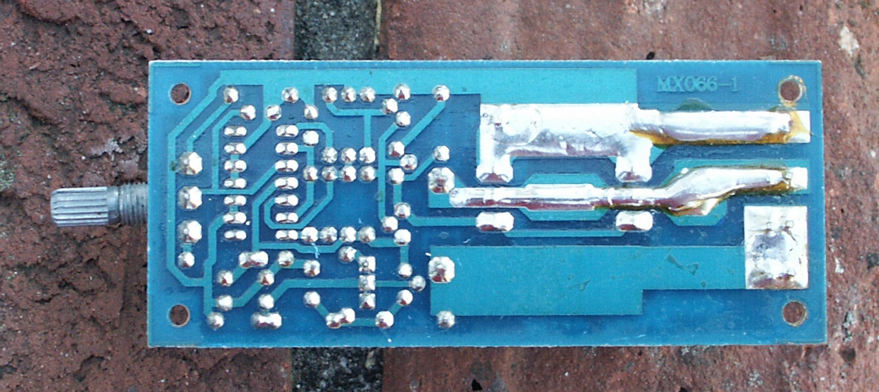
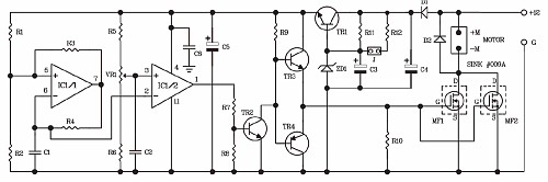
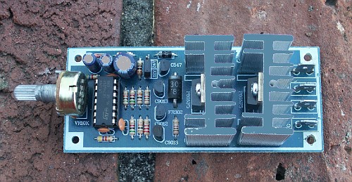
After looking at a few different circuits, i settled on the MX066 from
bakatronics.
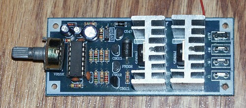

This circuit is based on the LM324 operational
amplifier (opamp) and is
designed to handle up to 30amps which is more than adequate for our
alternator voltage regulator control application. The 100Hz frequency
of this unit is
somewhat close to 125Hz that ford generates inside the pcm to control
the alternator. But if we want to raise the frequency of the pwm to
125Hz, we will need to lower the resistance of R4 in the circuit.
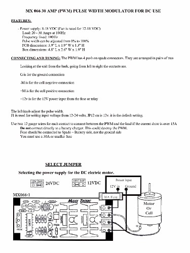
This circuit turned out to work very nicely to control the alternator
even though the frequency of the pwm waveform is 25 Hertz slower then
the ford gencom specifications in it's unmodified form.

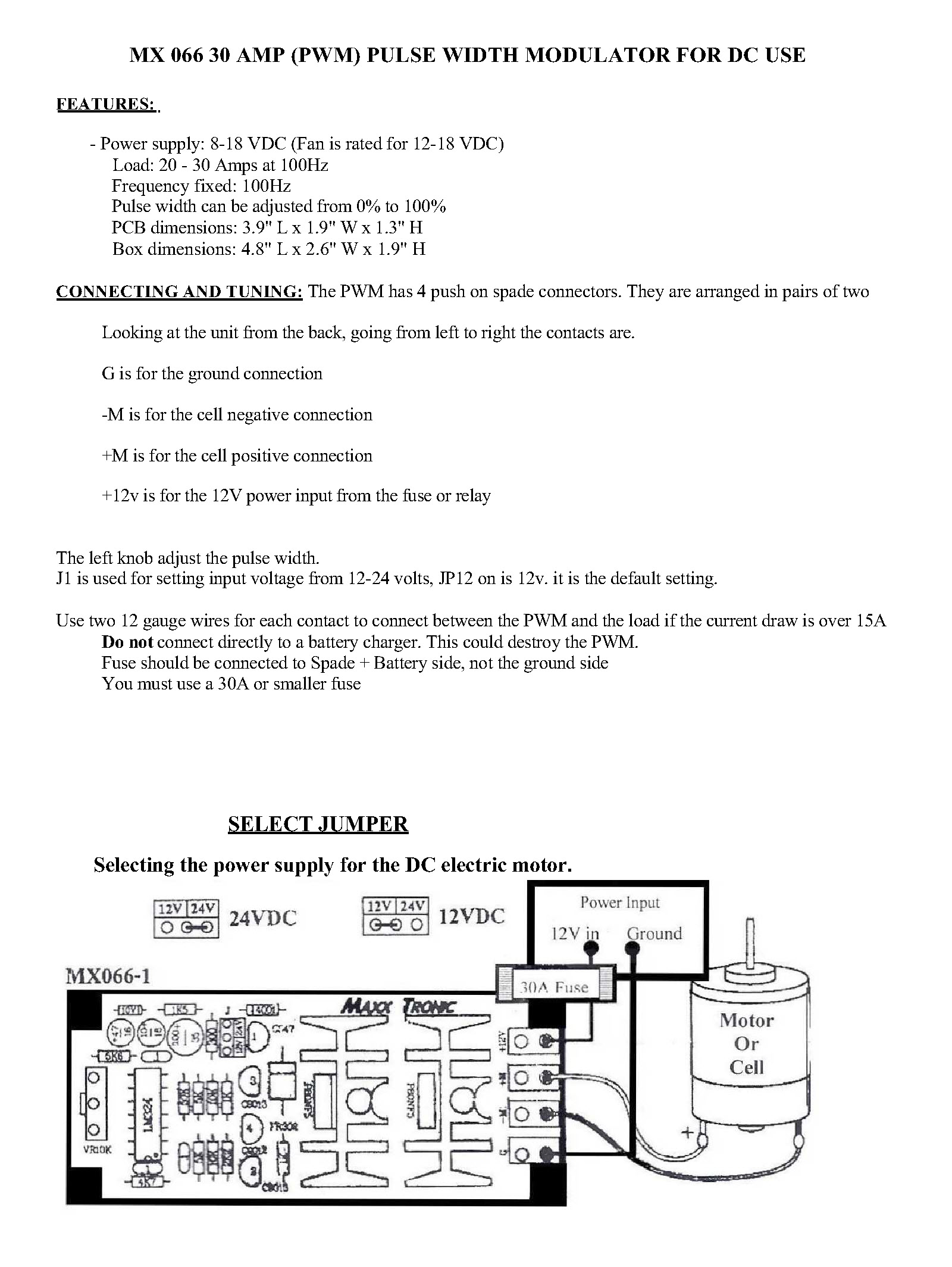
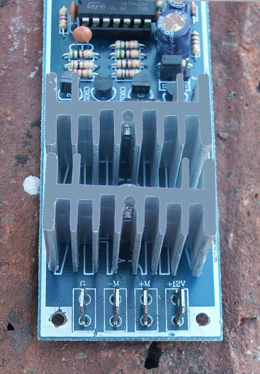
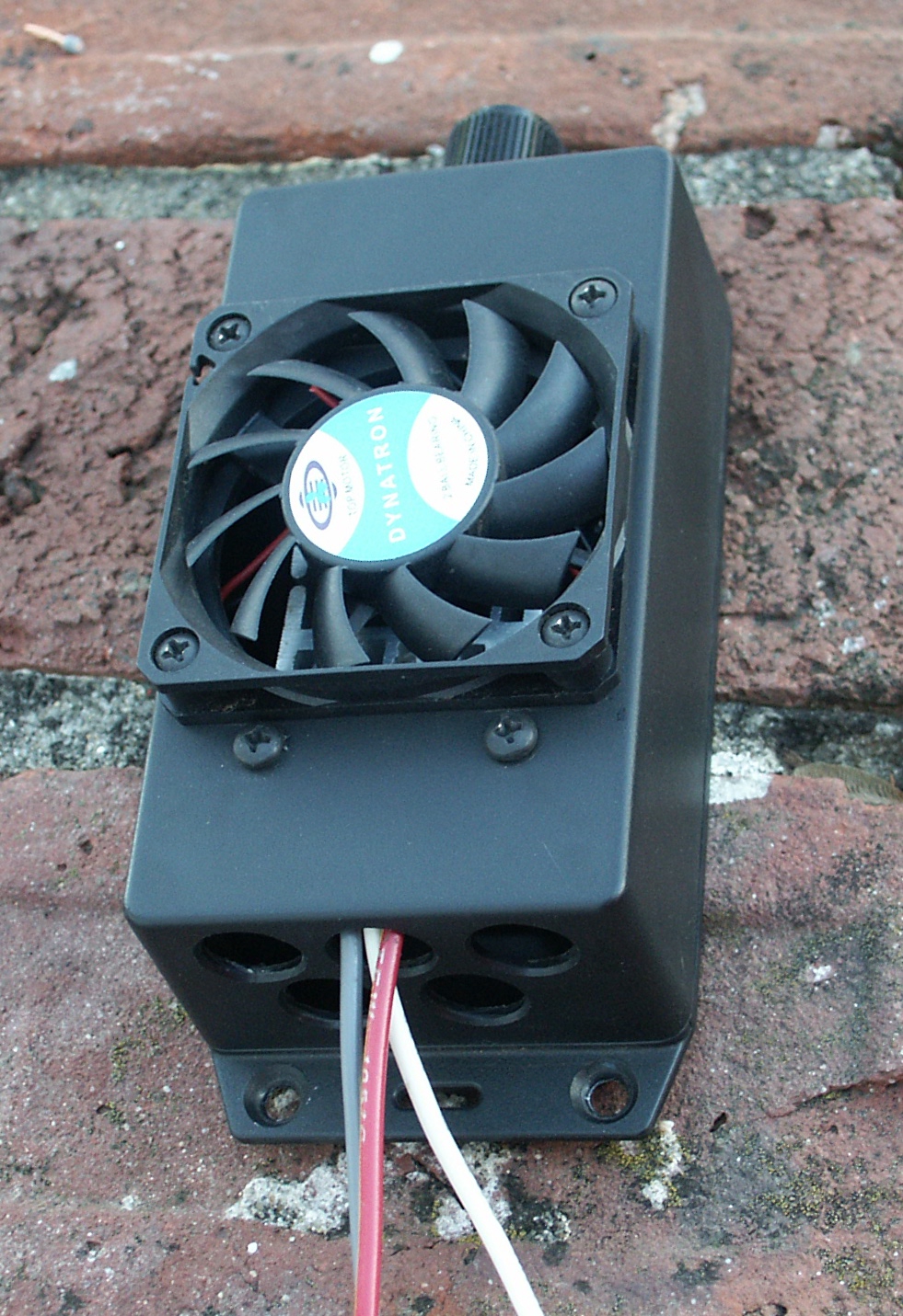
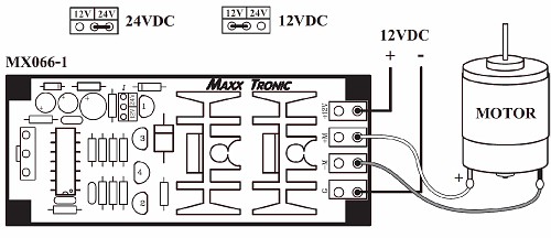
For our project, we want to crimp three 1/4" spade terminals onto 3
peices of wire and insert them onto these tabs. We will be using the G,
-M, and +12V terminals. The +M terminal will be unused since it jumps
directly to the +12V feed and our alternator already has an internal
source for +12V.
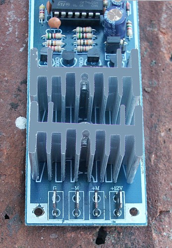
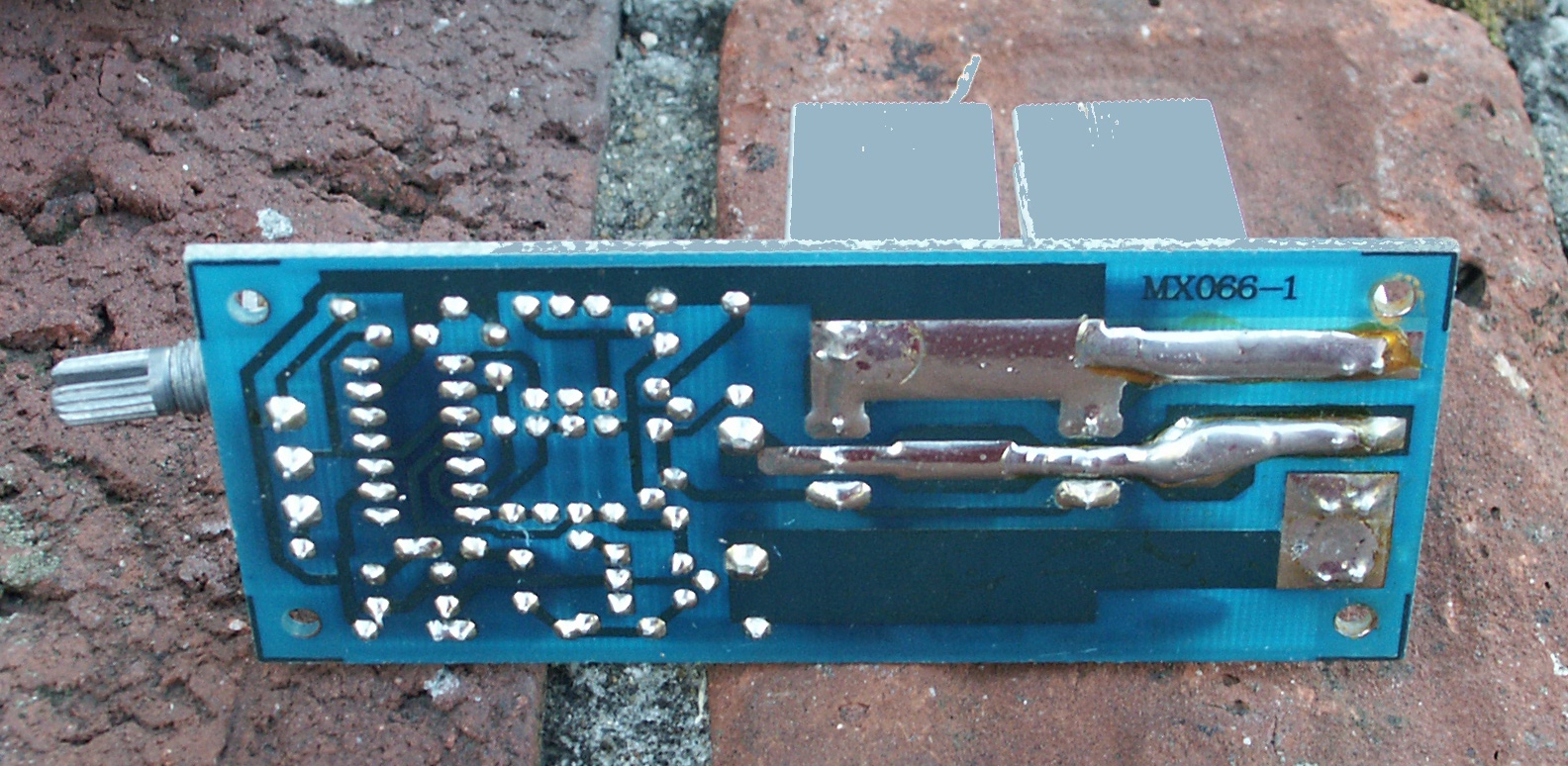
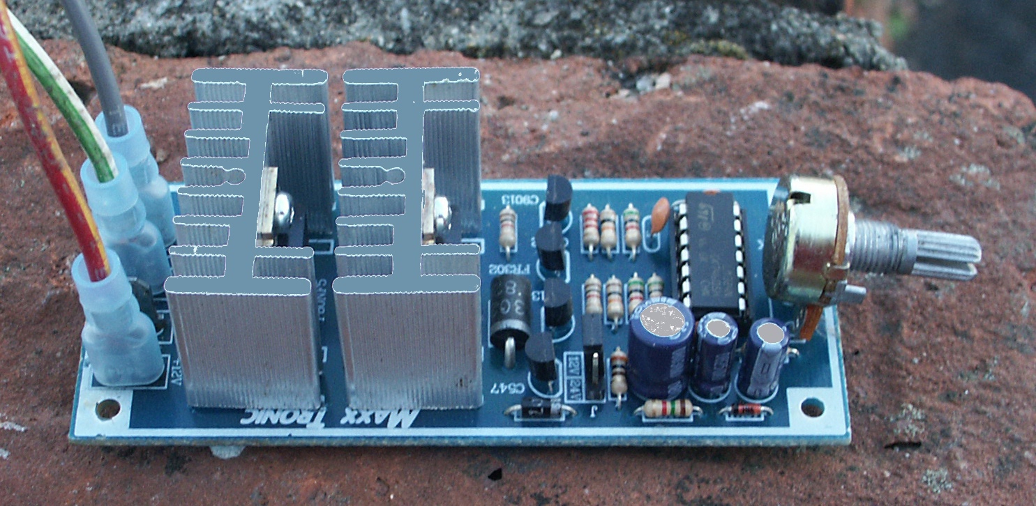
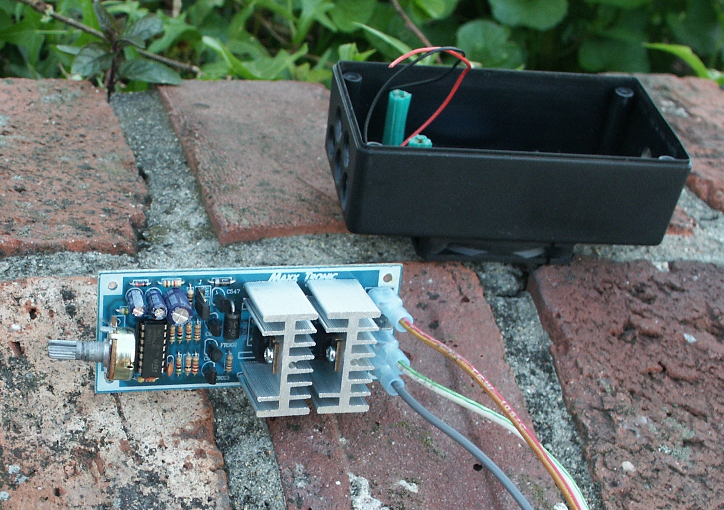
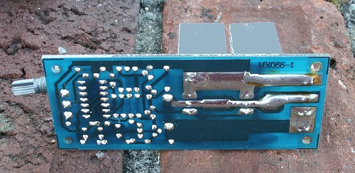
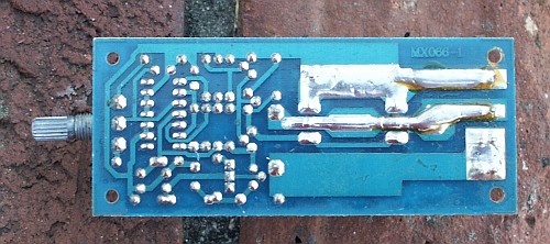
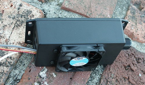
After crimping the wires and sliding them onto the circuit board

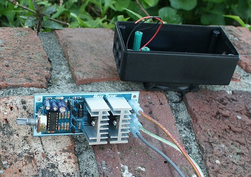
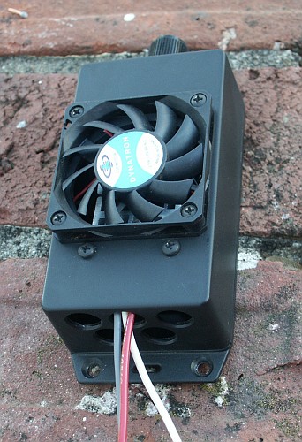
After inserting the circuit board into a case so that the traces don't
accidentally short out against metal objects
The red wire is +12V, the grey wire is ground, and the white wire is
the pwm output to feed the alternator gencom line.
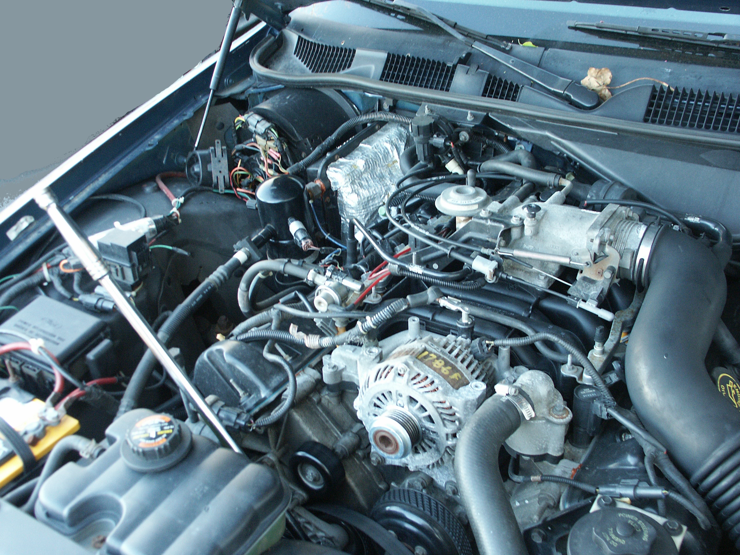
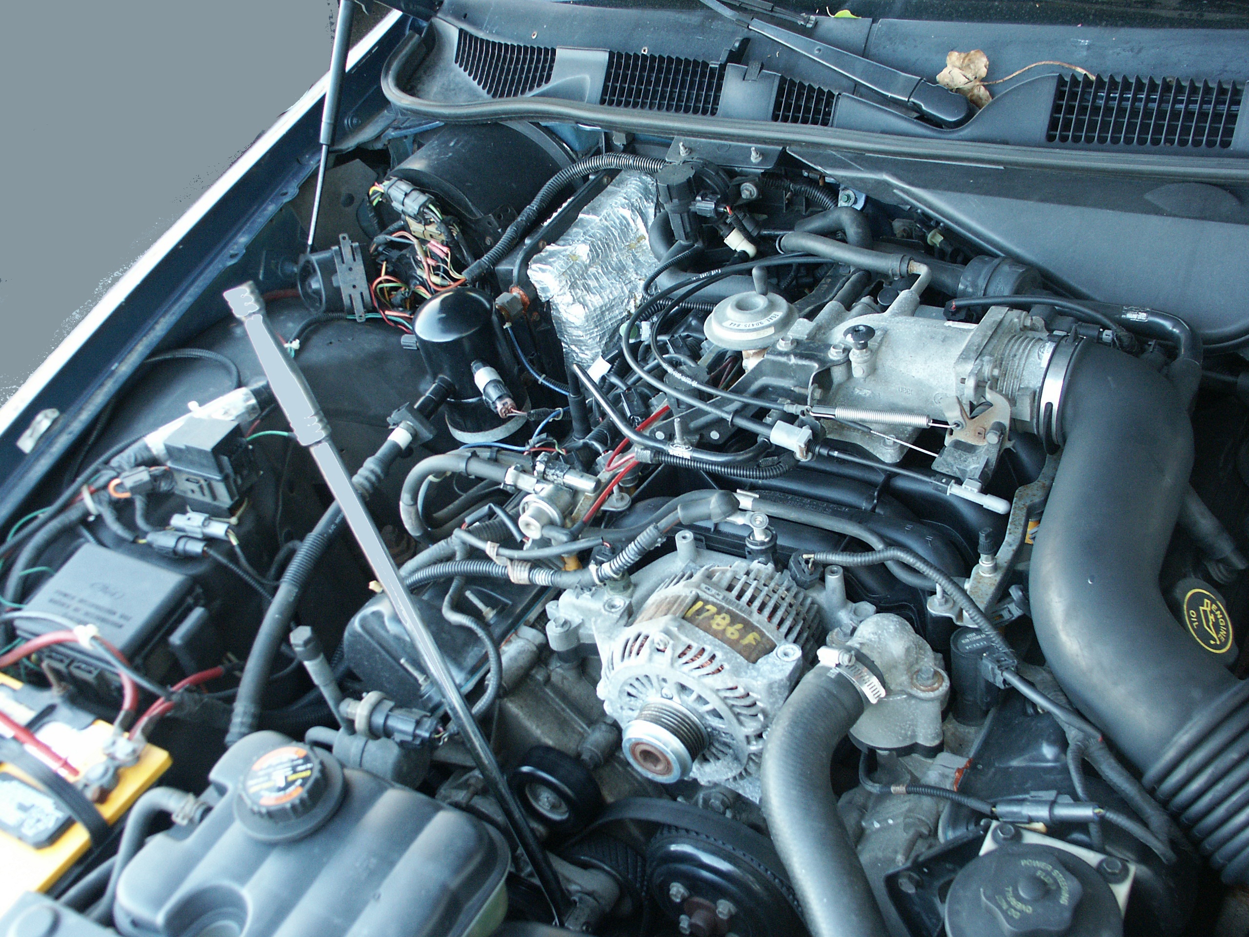
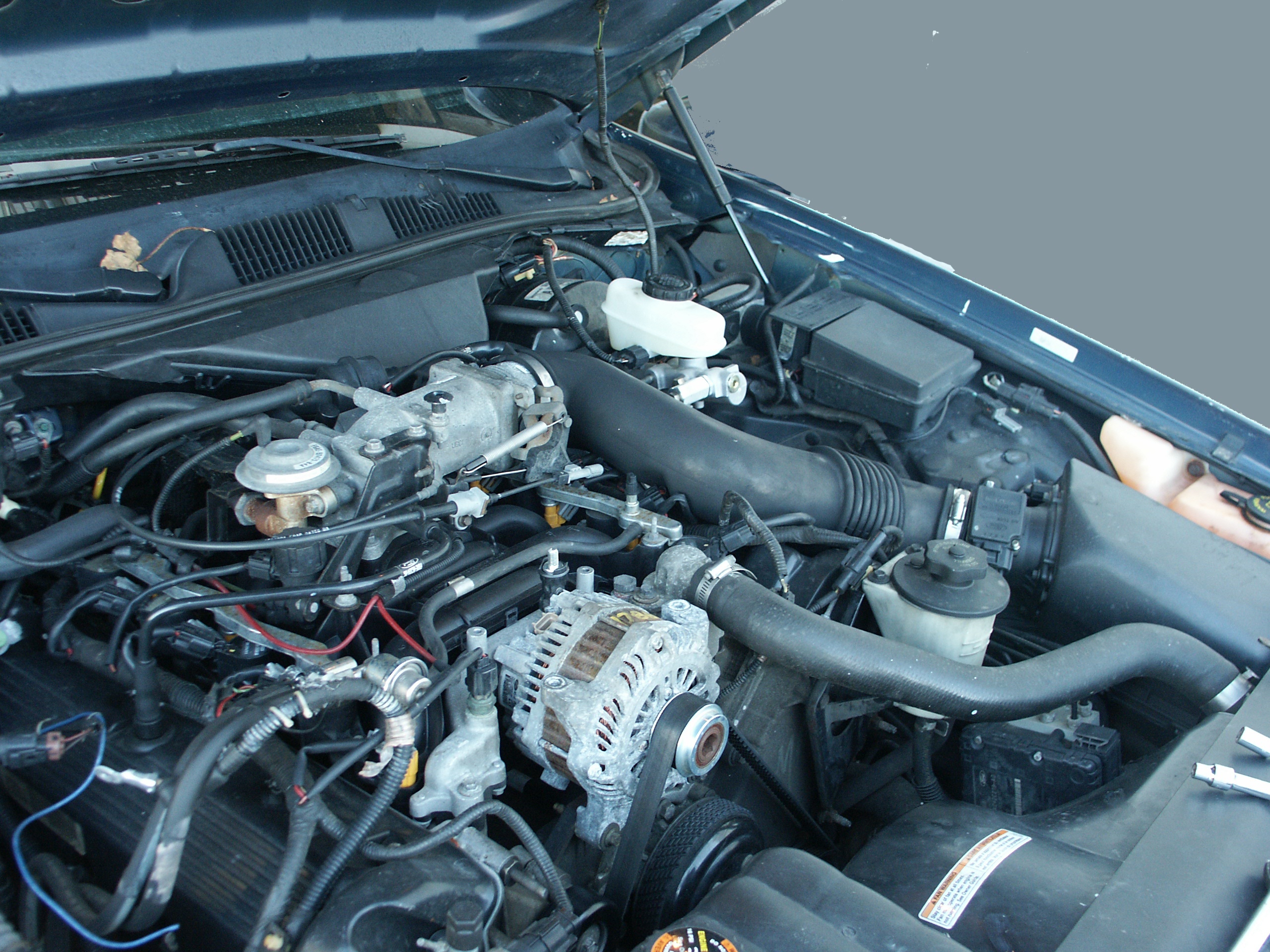
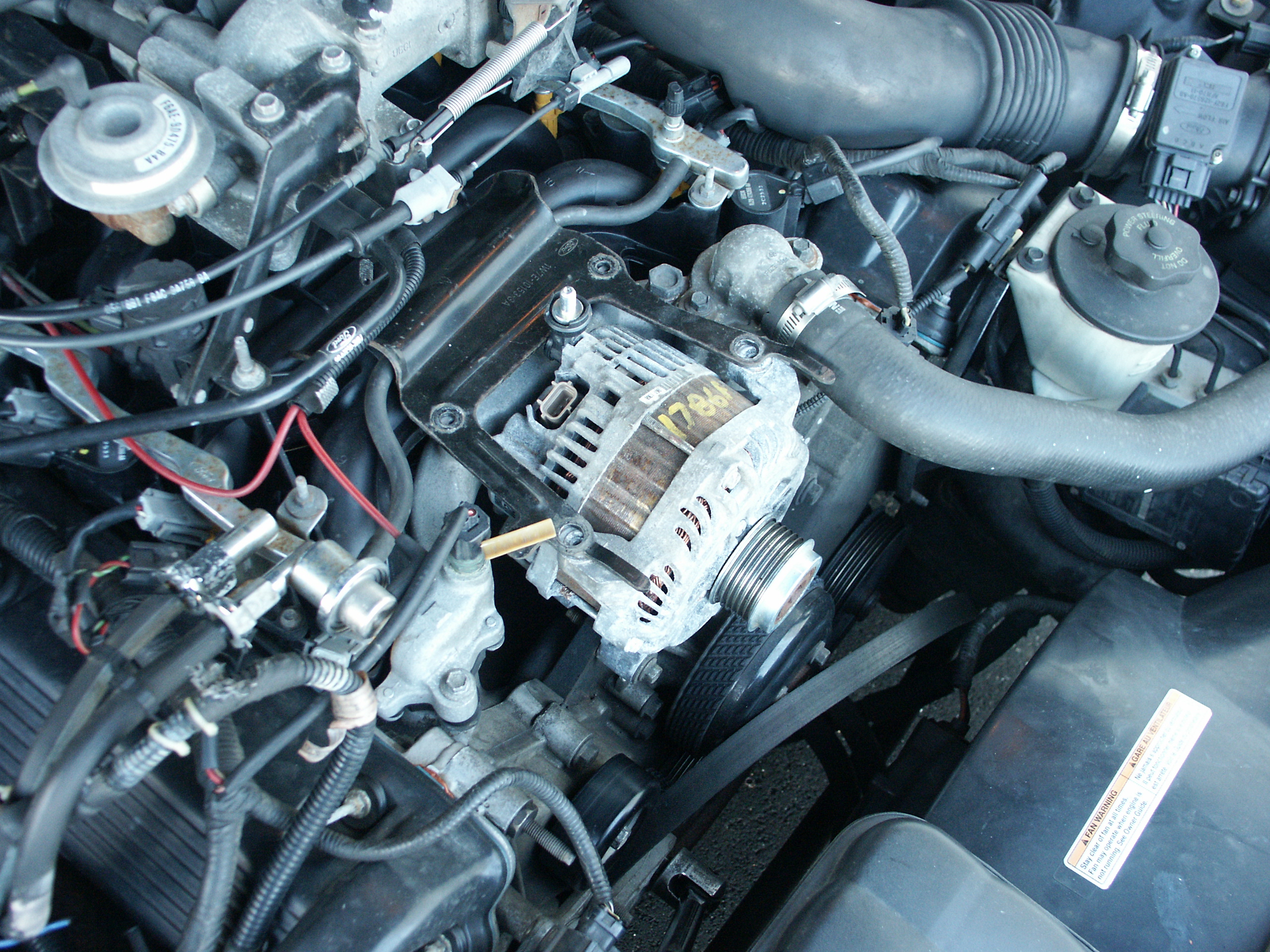
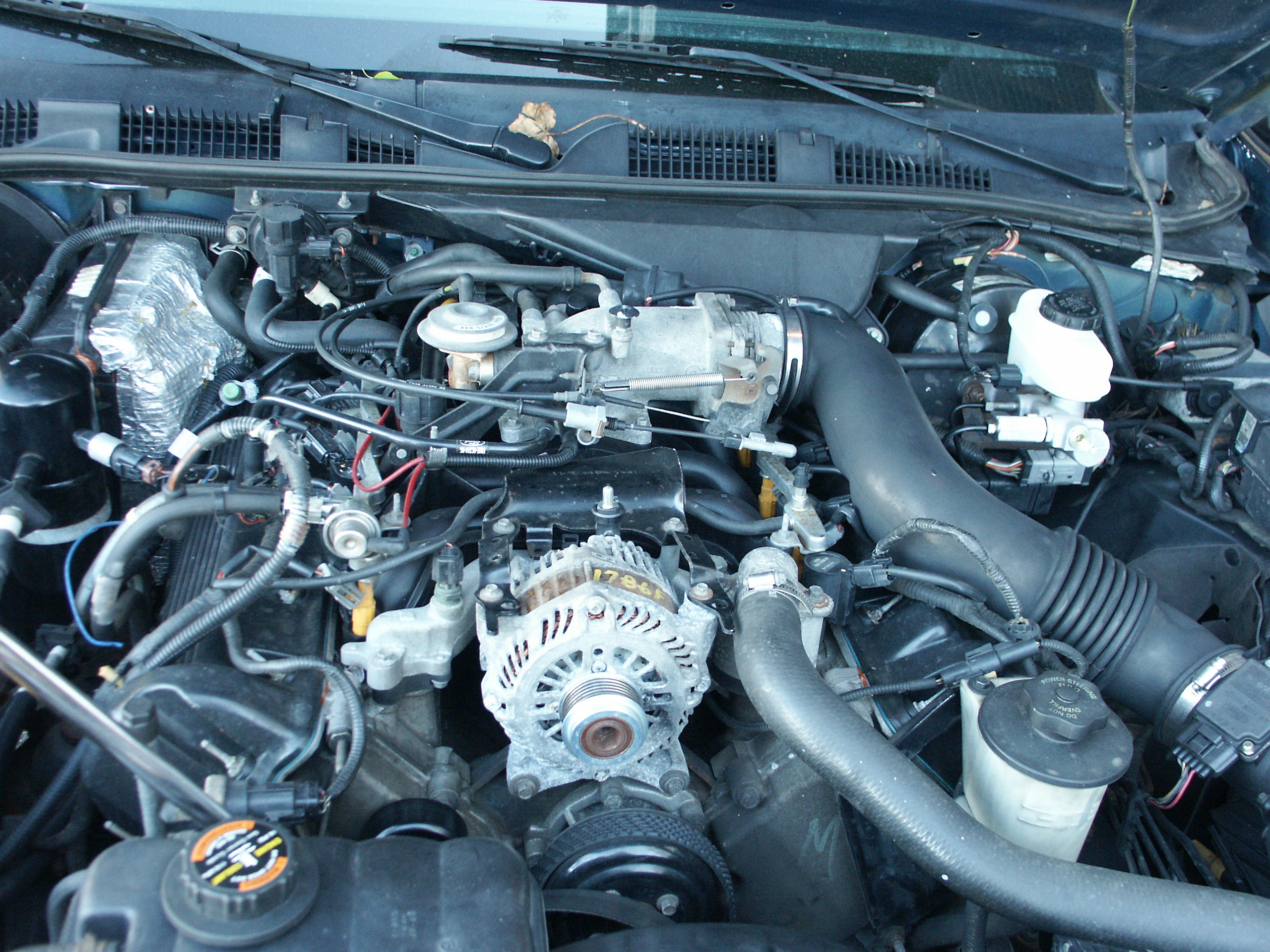
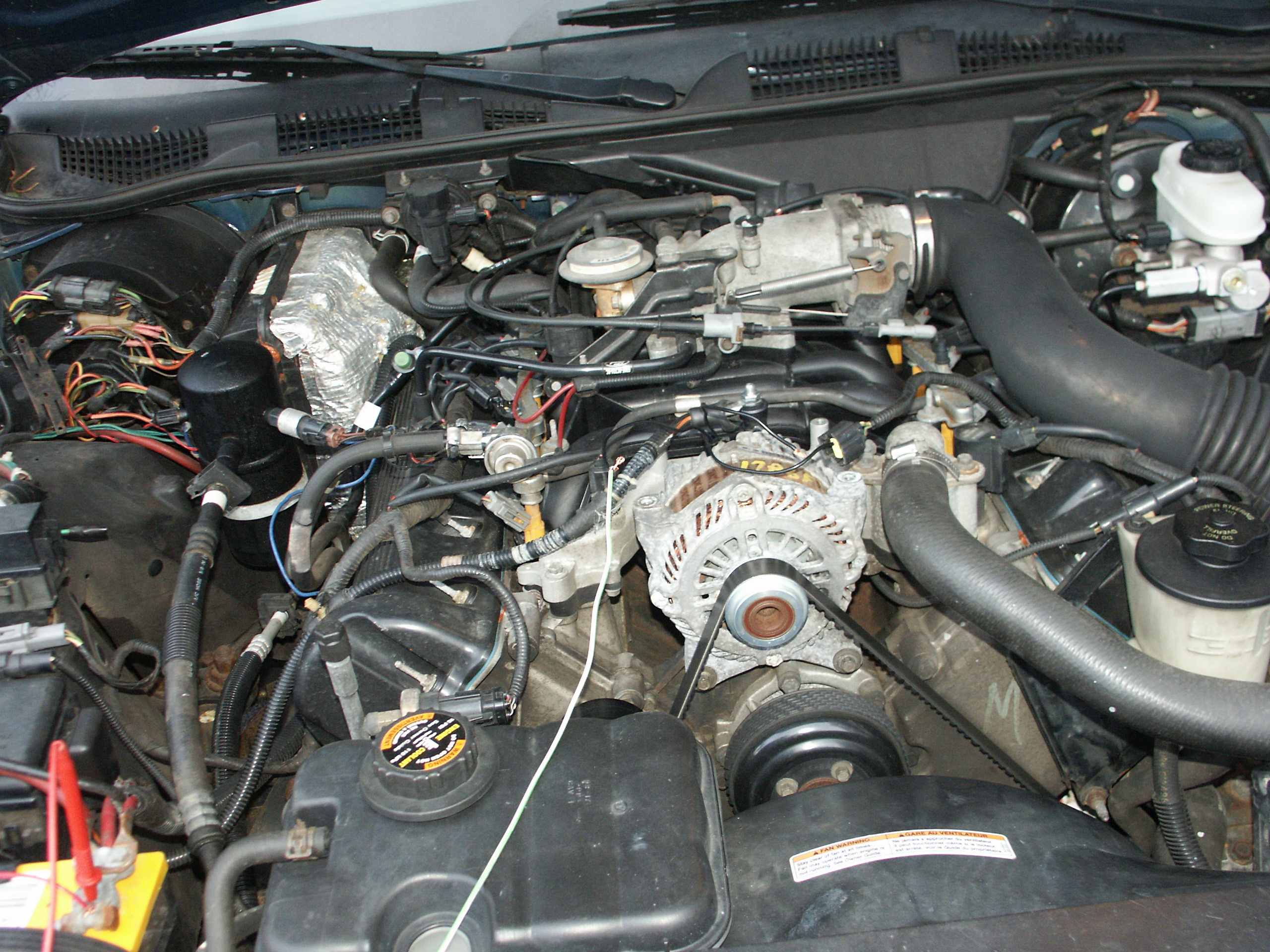
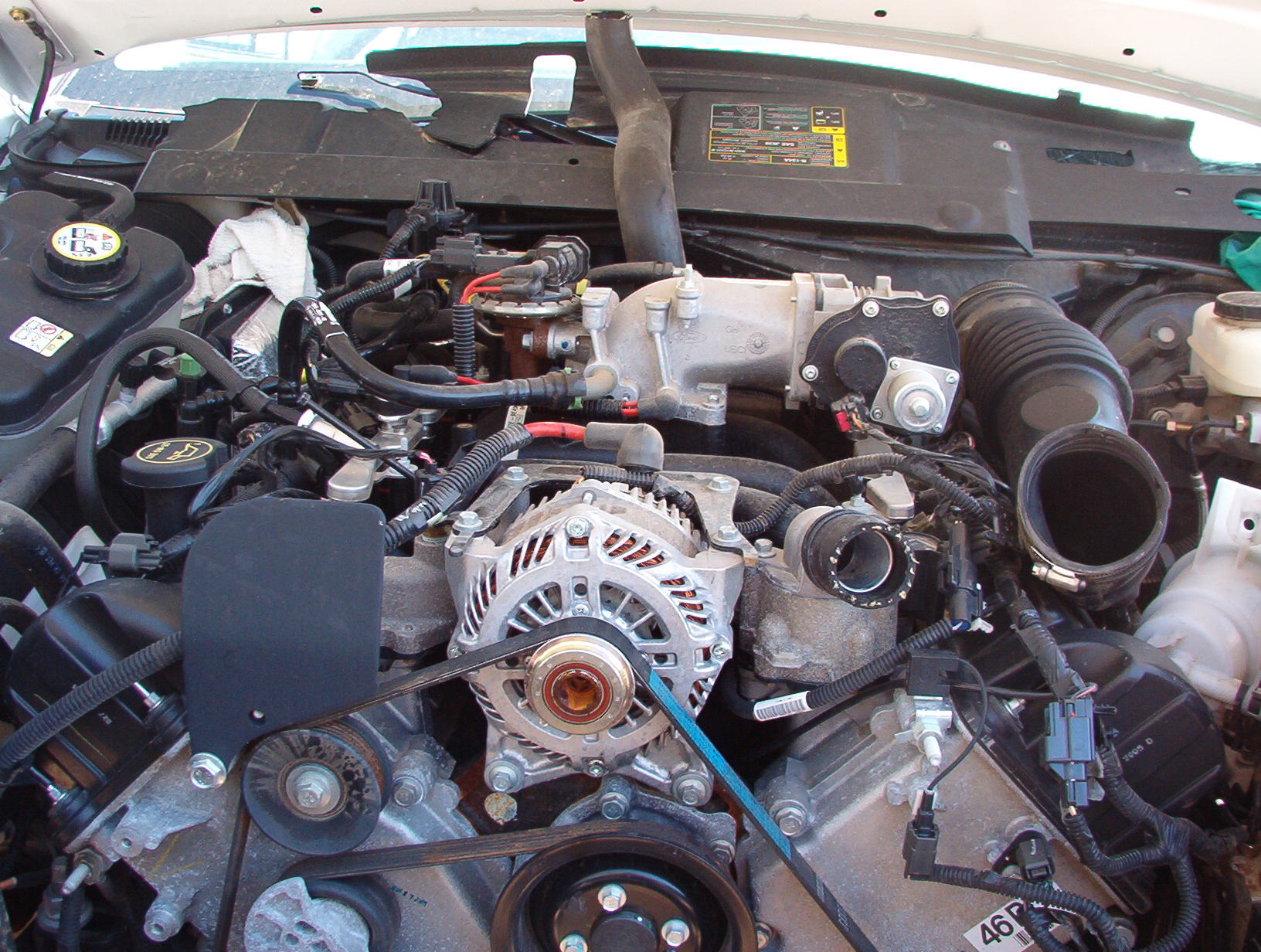
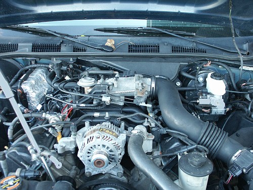
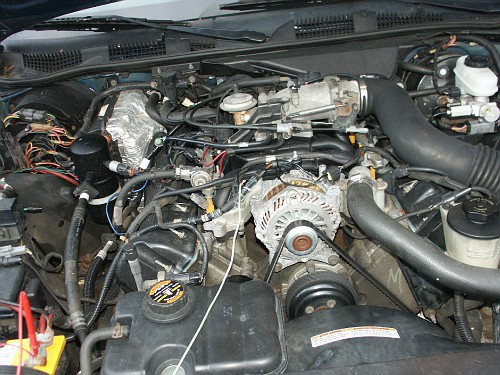
Here's our testbed vehicle with the 2009 alternator installed. A new
voltage regulator wiring pigtail was purchased, and one wire of the new
pigtail inserted into the appropriate pin of the old regulator
connector to read battery voltage. The middle gencom wire is connected
to the output of the pwm device. Turn the pwm control knob
counter-clockwise and we can raise the voltage setpoint
of the alternator regulator close to 15Volts. Spin it clockwise and the
setpoint will dip down below 12Volts at the other end of it's travel
limit. The alternator voltage setpoint is very stable with batery
voltage only varying +/- 0.01 Volts given a constant load on the car's
electrical system.
Good battery recharge characteristics are obtained somewhere between
14.0 Volts and 14.5 Volts at a reasonable ambient temperature. The
regulator in the factory installed 1998
crownvic alternator had a fixed setpoint of 14.4 volts according to
transpo, but battery
voltage was actually 14.1Volts at idle with the engine running and all
accessories turned off according to my voltmeter.
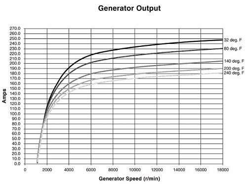
This is a really powerful alternator that ford under-rates. If you spin
the alternator really fast and the ambient temperature is low, you can
get well over 200 amps out of this unit.
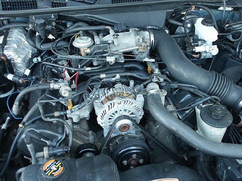
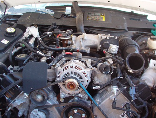
Here is a reference picture of a wrecked 2005 crown victoria engine
with the alternator and it's wiring attached
(picture courtesy of
Steve83 on www.crownvic.net)
Misc Notes:
- Upgrading a 2003-2010 crownvic to this alternator would have been
considerably easier since the powertrain control module (pcm) in these
cars already generates a pwm signal on the gencom line. The pcm in the
1992-2002 crownvics does not communicate with the alternator at all
other than the fact that it uses battery voltage for power.
- A little lesson about the basics of an alternator: To get power
out of
an alternator, you first need to send power from your car's battery
into the alternator to energize the rotor field windings. The rotor is
basically a big elecro-magnet that creates a big magnetic field when
electricity is applied to it. when the car is turned off, there is no
power going to the rotor windings. In the pre-2003 crownvics, when you
turn the ignition key on, battery voltage is applied to the rotor
windings by applying +12V to the charge indicator lightbulb on your
instrument panel, power then flows through the ~6 ohm bulb filaments to
the regulator which then sends power to the rotor field windings to
create a magnetic field. Once the engine starts spinning reasonably
fast, the alternator begins to produce electricity in the stator coils
which then turns off
the charge indicator bulb by applying +12V to the bulb feed wire at the
regulator. If both sides of a lightbulb are at +12V, the potential
difference between the two sides is 0V and the lightbulb will not be
lit.
- There are two different ways for an alternator to self excite.
Rotors usually have a small amount of residual magnetism in them and
when you spin them really fast, it's sometimes enough to get sufficent
magnetism induced into the stator windings to get the electricity out
of the windings so that a full strength magnetic field can be built up
and the alternator can output at full capacity. The disadvantage of
this setup is that you often need to rev up the engine to get the
alternator to self excite. But the alternator pulley is overdriven at
about a 3:1 ratio by the crankshaft, and police interceptors have an
initial cold idle speed of close to 1000RPM so the alternator shaft
would be spinning at 3000RPM. The other method of getting the rotor
magnetic field to turn on initially is to monitor battery voltage. A
big drop in battery voltage indicates the starter motor was cranking
the engine, and the rotor field coil can be turned on by the regulator
for a couple seconds.
- Instead of generating a fake gencom signal to simulate the pcm or
sending an altered signal to the voltage sense terminal of the
alternator regulator, you could in theory get one of these alternators
working in an earlier car by hacking up the internal voltage regulator
to pass the field coil signal to an external conventional i-line
regulator. Many 1970's ford vehicles used such a voltage regulator
setup, but you must be careful to make sure that your regulator can
handle the load of such a large rotor field coil. Also, be aware that
recent internally regulated ford alternators are a-circuit with rotor
field current controlled through the ground side of the circuit. And
most external ford regulators are b-circuit regulators with field
current controlled through the positive side of the rotor field circuit.
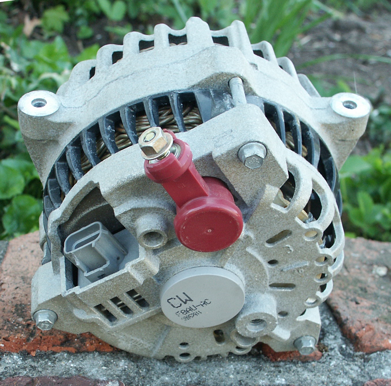
- The Alternator Regulator Pulls:
Voltage sense low (ground) (pin 1)
Genmon low (ground) (pin 3)
Gencom high (+12V) (pin 2)
- This 2009 police interceptor alternator would self excite without
any regulator wires connected.
- Without the remote voltage sense pin connected, the alternator
was in "machine sense" mode which sensed the voltage at the output post
and commanded output 0.2V higher than in remote sense mode.
- Conncting gencom to ground caused the alternator to stop charging
or set the voltage setpoint really low
- With no gencom pwm signal fed to the alternator, the genmon line
would stay at 0V for a while, and then start sending a +12V squarewave
signal to the gencom line, and then go back to 0V for a while and
repeat the process. Connecting the charge light bulb on my 1998
crownvic's dashboard to this wire would not illuminate the light
because this is a low current feed line not intended to drive a high
current light bulb.
- The alternator genmon line has a duty cycle of a little under 50%
under minimal loading. And the duty cycle will increase as alternator
load increases.
- The 6G alternator regulator connector used in 1998-2002 crownvics
does not have a wire in the middle pin of the connector. And the
connector shell is not designed to allow installation of a new pin in
this location either. To be able to send gencom data on pin 2, you will
need to replace this connector with a new WPT-118 service pigtail from
ford or one sourced from a wrecked 2003+ police interceptor donor car.
- It can be rather frustrating on a high mileage 2003+ crownvic
when the gencom or genmon wiring gets damaged and signals from other
circuits get into these wires. Drive over a bumpy road and you might
see your alternator charge at over 16 volts for a bit, then a while
later drop so low that the car stalls out because the powertrain
control module doesn't operate properly at voltages that low. If you
suspect problems on this circuit, run a couple new wires from the pcm
to the alternator regulator pigtail for the gencom/genmon signals.
These are just signal wires that don't carry any real amperage, and
16AWG or 18AWG should be good.
- Be careful not to leave the ignition "on" without the engine
running when the using a pwm device to control the alternator. The pwm
module will command the alternator rotor field coil to engage even
though the engine isn't running. This will cause the field coil to
generate a magnetic field and build up some heat too. When the engine
is running, the alternator cooling fans are spinning to move air across
the alternator components. When the engine is stopped, the cooling fans
are also stopped, and the heat can really build up. You shouldn't have
problems with this issue if you educate the drivers of your car not to
leave the ignition on without the engine running. If you have your pwm
device wired properly, turning the ignition key backwards to the
accessory position to listen to the radio is fine, it's just leaving
the ignition key in the run position without the engine running
that is bad. If you are really adventorous, it's possible to wire the
pwm circuit to monitor the engine oil pressure or fuel injector pulse
rate to shutoff the field coil when the engine is not running.
- The MaxxTronics pwm running with no load draws about 3 amps
- The pwm components were cool to the touch after driving the
alternator gencom lead for over an hour (even with pwm cooling fan
disconnected). This is to be expected when one is running a circuit
designed for thirty amps with only a few milliamps actually flowing
though it.
- The 200amp Mitsubishi alternator used in the 2004+ police
interceptors costs about $500 from your local ford dealership. The ford
3G, 4G, and 6G alternator are about half that price.
- The alternator pulley clutch in the 2004+ police interceptors
often wears out before the remainder of the alternator components have
failed. An alternator cannot charge if it's rotor is not spinning
because of a defective clutch. Early warning signs of impending
alternator clutch bearing failure include objectionable noises when the
transmission shifts during hard acceleration or objectionable noises
for a short period of time after you shut off your engine. The noises
after you shut off the engine are because the alternator rotor has a
decent amount of mass and continues to rotate, but the engine accessory
belt holds the alternator pulley stationary causing the clutch to
overrun.
- The mxa066 pwm has linear control over the regulator voltage
setpoint. At one end of the spectrum, the alternator charging output is
effectively shut off because the voltage setpoint is so low. At the
other end of the spectrum, the alternator output will climb close to 15
Volts. But there is an odd spot in rotating the knob after the voltage
peaks at 15Volts. After that point, the voltage abruptly drops to
13.2Volts and stays there for the remainder of the rotation range
instead of climbing higher. It is suspected that this is because the
pwm is outputting 100Hz instead of the 125Hz that the alternator is
designed to accept, and the alternator regulator goes to a failsafe
setpoint at this point.
- After installing the 200amp police interceptor alternator, you
will want to upgrade the 6AWG charging wire and the fuselinks which
protect
the charging wire from overload. The factory installed 4G and 6G
alternators use (one single 8AWG fuselink) or (two 12AWG fuselinks in
parallel) for circuit protection.
The police interceptor alternator uses two 10AWG fusible links in
parallel, but a 300amp aftermarket ANL car audio fuse should work
instead. Fusible link wires are basically very slow blow fuses
constructed of specially designed undersized wire with extra thick
insulation that can
withstand very high temperatures. Do note that current flows in a loop
and you need good ground wires too, but the factory installed ground
wire is already rather thick because it carries the full load of the
engine starter motor.
- The output battery post stud on the 200amp mitsuibishi alternator
is M8x1.25 which will have a diameter of approximately 8mm. To
construct a custom charging wire, ideally you would use a metric #8
ring terminal lug on the alternator end. But, these are not readily
avaliable and you will likely end up using an SAE 5/16" ring terminal
lug from an aftermarket autoparts store, car audio shop, or marine
boating supply store instead. 5/16
inches = 0.3125 inches = 7.9375 millimeters. Do not purchase an SAE
3/8" ring terminal lug because this is too large, 3/8 inches = 0.375
inches = 9.525 millimeters.
- If you downgrade back to a ford 6G alternator, the output
charging post stud is M6x1.0 which will have a diameter of
approximately 6mm. To construct a custom charging wire, ideally you
would use a metric #6 ring terminal lug on the alternator end. But,
these are not readily avaliable and you will likely end up using a SAE
1/4" ring terminal from your local autoparts store, car audio shop, or
marine boating supply store instead. 1/4 inches = 0.250 inches =
6.350
millimeters. If the mitsubishi alternator that you acquire has been
rebuilt before, there is also a possibility that the alternator
charging post will have an M6 stud instead of an M8 stud on it too.
- The battery cable post that the alternator charge wire connects
to on the underhood fuseblock of 1992-2002 crownvics is an M8x1.25
stud. Do note that the factory installed nut on this stud is odd in the
sense that it limits travel of the nut on the stud. So you can install
the M8x1.25 nut from a mitsubishi alternator onto this stud. But you
cannot install the fuseblock nut onto a mitsubishi alternator because
the indented area of the nut will grab against the alternator charging
post stud threads before it can be tightened down enough to properly
hold the charging wire in place.
- The oem ford alternator output wire ring terminal lugs have a
grey colored tin plating on them to protect against corrosion. The
actual terminal underneath the coating is made of a copper alloy. In
the aftermarket, ring terminal lugs are avaliable with and without the
tin coating. And ring terminal lugs are usually located in the car
battery or engine starter motor section of retail automotive parts
stores. In the aftermarket car audio world, many ring terminal lugs
come with gold plating appled to protect against corrosion. Gold and
tin are both effective at preventing corrosion of the underlying metal,
but some people prefer the cosmetic appearance of gold colored
electrical components over the dull grey color of the tin plated ones.
- It is also worth mentioning that a tutorial on
crimping battery cable ends is avaliable here.
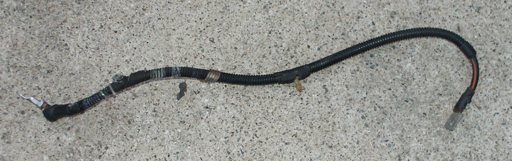
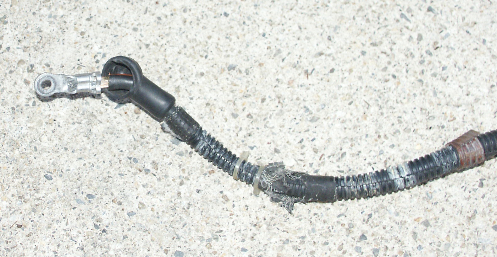
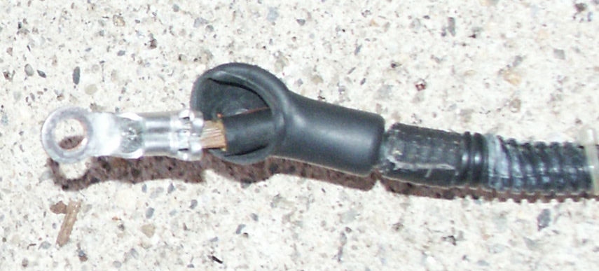
- Some pictures of the fusible links that are located between the
alternator output wire and the vehicle's battery on the 1998-2002
crownvics are avaliable on the
battery
cable
harness
webpage. Do note that the 1998-2002 crownvics
are somewhat odd in the sense that the alternator fuselinks are not
located in the charging wire that connects the alternator charging post
to the underhood fuseblock, but rather in the wire that connects the
fuseblock to the battery. In the 1992-1997 crownvics, the alternator
fusible links are located in the charging wire which connects the
alternator output post and the underhood fuseblock.
- A technical service bulletin about retrofitting the 200amp
mitsubishi high
output alternator into a 2003 crown victoria is avaliable by clicking here. A special service message
(ssm) from the ford oasis network about the powertrain control module
calibration referenced in the previous tsb is avaliable by clicking here.
- Some people may wonder whether it is possible to create their own
kit to make installing a 2004+ police interceptor alternator into their
civilian crownvic plug and play. This is possible, but it's also rather
expensive. First, you need to acquire a 2004+ crown victoria police
interceptor alternator, then you need to order the appropriate model
year police
interceptor battery cable harness (the alternator charging wire is
part of the battery cable harness in 03+ crownvics). And finally, you
need to order the little jumper cable extension harness which connects
the alternator regulator to the connector on the car's electrical
harness (part # 3W7Z-14A411-DA). Do note that you cannot use the
3W7Z-14A411-DA jumper harness on a 2003-2004 civilian crownvic, and
would need to replace the entire fuel/charging electrical harness. But
you might find it more cost effective to just cut-n-splice on a
1U2Z-14S411-TA (WPT-118) regulator pigtail onto your existing
fuel/charging harness, and custom fabricate something for the high
current alternator output wire instead.
- There is programming information inside the powertrain control
module specific to the alternator model that a crownvic originally had.
But some people have upgraded their 2003+ civilian crownvics from the
4G civilian alternators to the high output police interceptor
alternators by just splicing on a different alternator regulator
pigtail and upgrading the output wire. And some police interceptors
have had their 200amp mitsubishi alternators downgraded to the 135amp
6G alternators by just plugging in the new alternator. In both cases,
no driveability problems were reported despite not reprogamming the pcm.
- There has been some debate about whether the small electrical
extension harness extension is really needed to install a 2004+
alternator into an earlier vehicle that's wired for the ford 6G
alternator. Both alternators use the same electrical plug for the
regulator, but the cars with the mitsubishi alternator have a longer
regulator connector takeout than the cars with the factory installed 6G
alternator do. Some people have said that they were able to stretch
their fuel/charging wiring harness to reach the alternator regulator in
its new location by disconnecting some harness->engine retainers and
giving the harness a couple sharp pulls, but this is asking for
trouble. Attempting to elongate an electrical harness by stretching the
wires inside is going to damage the harness and could cause you
nightmare electrical problems in the future.
- There has also been some debate about whether the external
control box for the alternator regulator is really needed when
installing a 2003+ alternator into an earlier car. Some people are
adamant they installed pcm controlled 2003+ alternator into an earlier
car and it worked great without the external pwm box. While many 03+
alternator models will self excite and start charging if you install
them in an earlier crownvic, they will only charge at a little over
13Volts. This is too low a voltage for good battery charging
characteristics. The alternator might seem to work acceptably for a
brief period during
the warm summer months in a hot southern enviroment like florida. But
you're going to have problems starting your car's engine during the
winter months if you live in a cold enviroment like northern new
england or canada. Good battery recharge characteristics are obtained
somewhere between 14.0Volts and 14.5Volts. You can safely raise the
charging voltage a little beyond that on really cold winter days too.
- On internet discussion forums, you'll often see www.custombatterycables.com
recommended for supplies to make custom automotive battery cables.
There are also
a handful of vendors location on www.ebay.com
that sell similar supplies. Many people have also ordered automotive
battery cable supplies from www.genuinedealz.com.
This
place
caters
mainly to the marine boating crowd, but their cable
supplies work very nicely in an automotive enviroment too. Having
battery cables that are really resistant to water and salt corrosion is
a very good thing during the winter time in the northeastern united
states. The local highway departments in this area of the country apply
tons of chloride salts to the roads to melt snow/ice during the winter,
and the engine bay of a car driven on northeastern highways during the
winter will often look like a it has been operated in salt water marine
enviroment.
- TheShadow
on
www.crownvic.net commented "Does the Mitsubishi
allow for a larger overall diameter ring to be used? I'd be a little
leary about using an existing 135-amp circuit ring terminal and
boosting the current through it so much, and having to decrease its
cross-section at the same time. Possible work-arounds might be just
adding a washer to match the extra size (if any), or using a thicker
ring terminal." This is a very valid point. And in my case, the
alternator was just connected for temporary testing purposes this way
while I let the car idle in the driveway for a few hours with the hood
open. Something else is going to be custom fabricated when the
mitsubishi alternator upgrade becomes a permanent installation.
- Wiring diagrams for ford crown victorias and
mercury grand marquises are avaliable if you click here.
- For possible mounting locations for the pwm: you could mount the
pwm module to the driver's side of the rear seat strainer in the trunk,
this is where the factory keyless entry module used to be mounted in
the 1992-1994 crownvic lx's. On the 1998-2002 crownvics, there is also
an unused location down low in the passenger's side a-pillar near the
door hinges where the airbag crash module used to be located in the
1992-1997 crownvics. The technicians at your local car alarm and remote
start installation shop can likely think of other mounting locations
for you too, but you must not mount the pwm under the hood because this
area has lots of water passing through and electronics are easily
damaged by water.